
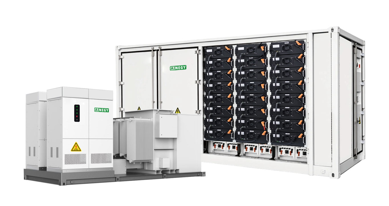
AINEGY 5MW/10–20MWh Grid-Connected BESS Integrated Cabin
A high-capacity grid-connected energy storage platform engineered around the complete power path from battery energy to an 11kV project grid interface.
The AINEGY 5MW Grid-Connected BESS Integrated Cabin is available with 10MWh or 20MWh battery capacity. The utility-scale energy storage system combines battery containers, BMS, 5MW PCS, EMS, liquid cooling, fire protection and 5500kVA transformer matching for grid-side, renewable integration and large industrial energy storage projects.
A 5MW Grid-Connected Energy Storage Platform, Not Only a Battery Container
Large grid-connected energy storage projects require more than battery capacity. Battery voltage, PCS power conversion, AC current, transformer matching, grid voltage and system control must form one clear electrical architecture.
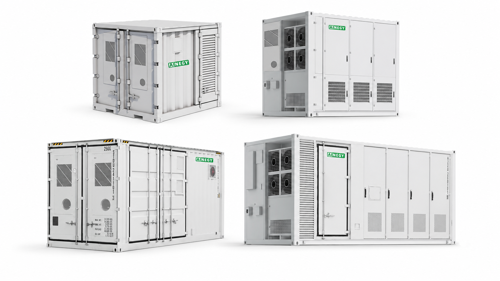
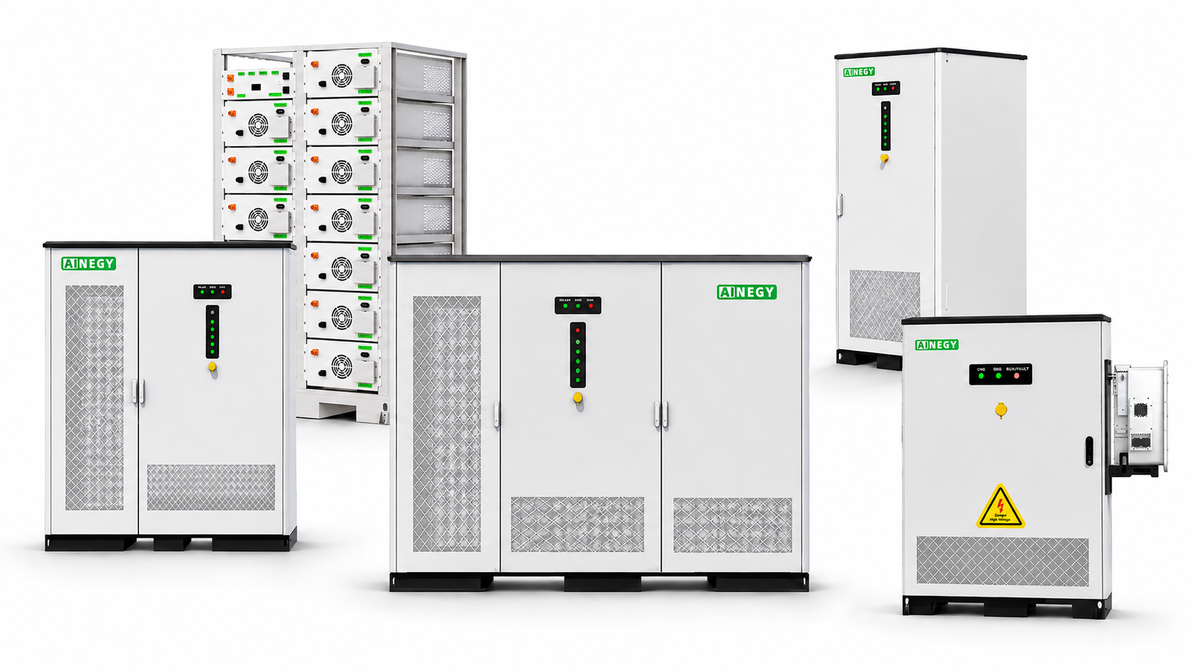
For broader product-form comparison, review AINEGY Containerized BESS and the Containerized Battery Energy Storage Systems category.
5MW Power Conversion for Both Energy Configurations
Both models use a 5MW PCS power class, allowing project selection to focus on required battery energy and nominal storage duration.
Select 10MWh or 20MWh Battery Energy
The system can be configured with two or four battery container modules according to the selected energy capacity.
690Vac Power Conversion to 11kV
A 5500kVA transformer matches the PCS low-voltage side to the specified 11kV high-voltage grid interface.
Supports Multi-Unit Parallel Deployment
Multiple systems can be engineered in parallel for projects requiring higher total power or energy capacity.
AINEGY Engineering and Quality Support
MW-level grid-connected storage requires system engineering across battery management, power conversion, energy management, thermal control, communication and grid-side electrical interfaces. AINEGY approaches the product as one integrated power-system project.
Years of BMS / EMS Technology Accumulation
Long-term development experience in battery-management and energy-management technologies.
R&D Team Members
Engineering support across BMS, EMS, inverter technology, battery integration and customized energy storage systems.
Countries and Regions
International project experience across different grid, communication and environmental conditions.
Cumulative Battery Shipment
Manufacturing and delivery experience supporting battery integration and international project execution.
Engineer the Complete Battery-to-Grid Power Path
Battery voltage, PCS DC range, 690Vac output and 11kV transformer interface are treated as one connected electrical architecture.
Validate Battery, PCS, EMS and Communication Interfaces
System validation focuses on operating status, communication and the power-conversion interfaces that connect the storage system.
Match the BESS to the Real Grid Connection
Grid voltage, project power, energy duration, communication, protection and site layout should be confirmed before final configuration.
5MW/10MWh and 5MW/20MWh Grid-Connected BESS Technical Specifications
The two configurations share a 5MW PCS platform, 1331V battery nominal voltage, 1000–1500Vdc PCS range, 690Vac AC side and 5500kVA transformer matching to an 11kV high-voltage interface.
| Item | 5MW / 10MWh | 5MW / 20MWh |
|---|---|---|
| Model | IYP-CB10ML-5MG3-HX1 | IYP-CB20ML-5MG3-HX1 |
| System | ||
| System Battery | 10MWh | 20MWh |
| System PCS | 5MW | 5MW |
| Battery Container | ||
| Battery Energy | 10MWh | 20MWh |
| Nominal Voltage | 1331V | 1331V |
| Battery Container Module Number | 2 | 4 |
| Size | 6058 × 9752 × 2896mm | 6058 × 9752 × 2896mm |
| Approximate Weight | About 44000kg | About 44000kg |
| PCS Cabinet | ||
| PCS Power | 5MW | 5MW |
| DC Voltage Range | 1000V–1500V | 1000V–1500V |
| AC Voltage | 690Vac | 690Vac |
| AC Current | 4180A | 4180A |
| Transformer | ||
| Rated Power | 5500kVA | 5500kVA |
| LV Voltage | 690Vac | 690Vac |
| HV Voltage | 11kV | 11kV |
| General Parameters | ||
| Communication Type | RS485 / WiFi / Ethernet | RS485 / WiFi / Ethernet |
| Battery Protection Rating | IP65 | IP65 |
| Fire Protection System | Yes | Yes |
| Operating Temperature | -10°C to 55°C | -10°C to 55°C |
| Humidity Range | 5%–95% | 5%–95% |
| Altitude | <2000m | <2000m |
| Battery Cooling Method | Liquid cooling | Liquid cooling |
| PCS Cooling Method | Intelligent cooling | Intelligent cooling |
| Multiple Units in Parallel | Supported | Supported |
Grid Connection Data
- Point-of-connection voltage
- 11kV project interface requirements
- Protection and metering requirements
- Medium-voltage switchgear arrangement
Power and Energy Requirement
- Required MW charge and discharge power
- Required MWh energy capacity
- Target storage duration
- SOC reserve and operating window
EMS and Communication
- Project control strategy
- Battery and PCS operating visibility
- Communication protocol requirements
- Local and remote integration requirements
Site and Environment
- Ambient temperature and altitude
- Container and equipment layout
- Transport and lifting access
- Operation and maintenance clearance
From 1331V Battery Energy to an 11kV Grid Connection
The technical value of this 5MW BESS is visible in its complete electrical path. Battery containers, power conversion and voltage transformation are matched around one grid-connected system architecture.
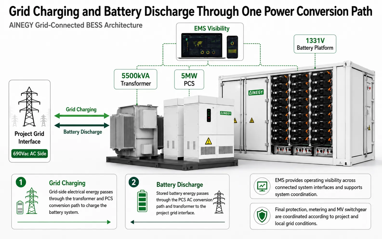
Grid Charging and Battery Discharge Through One Power Conversion Path
A grid-connected BESS must support energy movement between the battery system and the project grid. The AINEGY architecture connects the 1331V battery platform to the 5MW PCS, 690Vac AC side and 5500kVA transformer interface.
Two Operating Directions, One Grid-Connected BESS Architecture
The product should be understood as an energy storage power system rather than a one-way battery output device. Charging and discharging use the connected battery, PCS, transformer and grid interfaces in opposite energy-flow directions.
11kV Grid to Battery Energy Storage
The grid-side path supplies energy through the voltage-transformation and power-conversion stages before energy is stored in the battery system. EMS coordinates operation according to the configured project strategy and operating limits.
Battery Energy Storage to the 11kV Grid
Stored energy passes through the 5MW PCS conversion path and the 690Vac-to-11kV transformer interface before reaching the configured grid connection point.
5MW PCS and 5500kVA Transformer Matching for 11kV Grid Projects
PCS power and transformer matching define the conversion path between battery energy and the medium-voltage project grid. The AINEGY system specifies a 5MW PCS and a 5500kVA transformer with 690Vac low-voltage and 11kV high-voltage sides.
PCS Power
Shared power-conversion class for both 10MWh and 20MWh battery configurations.
PCS DC Range
High-voltage DC operating range for the battery-side power-conversion path.
PCS AC Interface
Defined AC-side voltage and current parameters for the 5MW PCS platform.
Transformer Interface
Voltage transformation from the 690Vac low-voltage side to the specified 11kV high-voltage side.
AINEGY EMS Monitoring and Grid-Connected System Coordination
The 5MW power path creates several connected operating interfaces. AINEGY EMS provides system-level operating visibility and supports dynamic control according to current system conditions and the configured project strategy.
Operating Visibility Across the Connected Energy Interfaces
AINEGY EMS observes the operating status of connected system interfaces and coordinates system operation according to the configured control strategy. The system architecture combines EMS with BMS and PCS operation instead of treating each device as an isolated component.
Liquid Cooling for 10–20MWh Battery Thermal Consistency
In a high-capacity grid-scale BESS, thermal management is a battery-system operating consideration. Liquid cooling provides a direct thermal-management path across the battery architecture during repeated grid charging and discharging.
| Battery Thermal Consideration | Airflow-Based Thermal Management | AINEGY Liquid-Cooled 10–20MWh BESS |
|---|---|---|
| Heat-transfer path | Relies more heavily on conditioned airflow and internal air distribution. | Uses liquid cooling to create a direct thermal-management path around the battery system. |
| High-capacity architecture | Air circulation paths must be considered across a dense battery arrangement. | Applied to 10MWh and 20MWh battery configurations within the AINEGY platform. |
| Repeated operation | Thermal behavior depends strongly on airflow distribution and duty conditions. | Designed to support thermal consistency during repeated grid charging and battery discharge. |
| Battery operating conditions | Air distribution can influence thermal conditions across battery areas. | Liquid cooling supports more consistent battery operating conditions across the high-capacity system. |
| System objective | Maintain acceptable battery and enclosure operating temperatures. | Support high-capacity battery integration and predictable thermal-management conditions. |
Battery Protection and Fire Protection Architecture
The product specification identifies IP65 for the battery protection rating and confirms a fire protection system. These functions sit alongside BMS monitoring, liquid cooling and system communication within the battery energy storage architecture.
IP65 Battery Protection Rating
IP65 applies to the battery protection rating stated in the product specification, not automatically to every external system component.
Battery Management as a Core System Layer
BMS is integrated into the product architecture to support battery-system operating visibility and management.
Fire Protection System Included
The product specification confirms a fire protection system. Final project fire-protection requirements should be coordinated during engineering.
Liquid-Cooled Battery Architecture
Battery thermal management is handled through liquid cooling, while PCS cooling is specified as intelligent cooling.
Factory Integration and System Interface Validation
A high-end 5MW BESS should be evaluated as a connected electrical system. AINEGY focuses on battery-system operation, BMS communication, PCS response, EMS visibility and the interfaces that link energy storage to the transformer and grid-side architecture.
Battery-System Operating Checks
Review battery-system operation and BMS communication within the high-capacity storage platform.
Power-Conversion Interface Review
Check PCS operating response and communication across the DC and 690Vac power-conversion interfaces.
System Operating Visibility
Verify communication paths used by EMS to observe connected operating status and coordinate the configured strategy.
690Vac to 11kV Matching
Review the PCS AC interface and transformer voltage path within the project electrical architecture.
Quality Built Through System-Level Engineering
Battery capacity alone does not define a utility-scale BESS. The connected interfaces between the battery system, PCS, EMS, transformer and project grid determine how the complete energy storage system is engineered.
Multi-Unit Parallel Expansion for Larger Grid-Scale BESS Projects
The product information states that multiple units can operate in parallel. This gives project engineers an expansion path when a single 5MW power block or 10–20MWh battery configuration does not meet the total project requirement.
Scale Beyond One 5MW Power Block
Parallel project architecture can be considered when total system power exceeds one 5MW configuration.
Build Higher Total MWh Capacity
Multiple systems can be coordinated when project energy capacity extends beyond one 10MWh or 20MWh system.
Coordinate Multi-Unit Operating Status
Communication and EMS strategy should be engineered around the connected system architecture and project operating requirements.
Review the Complete Grid Interface
AC bus, protection, metering, transformer arrangement and medium-voltage grid connection require project-level engineering.
Applications for AINEGY 5MW/10–20MWh Utility-Scale Grid-Connected BESS
Designed for MW/MWh-level projects where large battery capacity, 5MW power conversion and medium-voltage grid connection form part of the project electrical architecture.
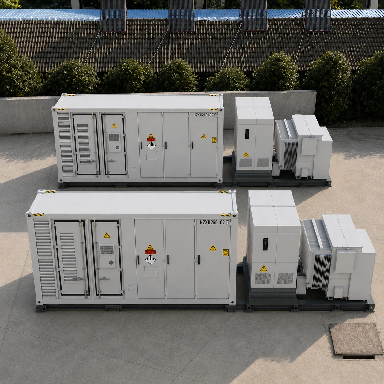
MW-Level Battery Storage for Grid-Connected Projects
Grid-side projects require clear coordination between battery energy, PCS power and the project medium-voltage interface.
AINEGY connects 10–20MWh battery capacity to a 5MW PCS and 11kV transformer path within one project-oriented architecture.
Project-Level Storage for Renewable Generation
Solar and wind projects can require large grid-connected battery storage as part of the wider AC project architecture.
The 5MW BESS platform provides a defined battery, PCS and transformer path for utility-scale energy storage integration.
10–20MWh Storage for Large Industrial Energy Systems
Industrial parks may operate substantial electrical loads and require MW-level storage within the site energy architecture.
The 10MWh and 20MWh configurations give project engineers two energy-capacity options around a common 5MW PCS platform.
Defined 690Vac-to-11kV Power Path
Projects with an 11kV interface require PCS and transformer parameters to be coordinated with the wider electrical design.
AINEGY specifies 690Vac PCS output and 5500kVA transformer matching to an 11kV high-voltage side.
Large Energy Storage for Grid-Connected Industrial Infrastructure
Large extraction and energy sites may combine substantial electrical demand with project-specific grid and distribution infrastructure.
The 5MW power class and 10–20MWh battery range support evaluation for large grid-connected industrial storage projects.
A Defined BESS Power Block for Project Engineering
EPC and system-integration projects need clear battery, PCS, transformer and communication boundaries.
AINEGY provides a defined 5MW power-conversion and 10–20MWh battery platform for project configuration and multi-unit expansion.
5MW Utility-Scale BESS Engineering FAQ
Clear answers to the technical questions that project developers, EPC teams and energy-system engineers commonly need before selecting a 10MWh or 20MWh grid-connected battery energy storage system.
It is a utility-scale grid-connected battery energy storage platform available in 5MW/10MWh and 5MW/20MWh configurations. The system combines battery containers, BMS, 5MW PCS, EMS, liquid cooling, fire protection, 5500kVA transformer matching and an 11kV grid connection path.
Both configurations use a 5MW PCS platform. The 10MWh model uses two battery container modules, while the 20MWh model uses four battery container modules and provides twice the nameplate battery energy.
Yes. Both the 10MWh and 20MWh configurations specify 5MW system PCS power, a 1000V to 1500V DC range, 690Vac AC voltage and 4180A AC current.
The 1331V battery platform connects through the 5MW PCS power conversion path. The PCS operates on a 1000V to 1500V DC range and 690Vac AC side. A 5500kVA transformer matches the 690Vac low-voltage side to the 11kV high-voltage grid connection.
AINEGY EMS provides operating visibility across connected system interfaces and can observe battery status, PCS operating status, system power flow, communication status and grid-side operating conditions according to the configured project control strategy.
Liquid cooling provides a direct thermal-management path across the high-capacity battery system and is designed to support more consistent battery operating conditions during repeated grid charging and discharging.
The product specification lists IP65 for the battery protection rating and confirms a fire protection system. Project fire-protection and site integration requirements should be reviewed during engineering.
Yes. The product information states that multiple units can be used in parallel. The final power architecture, EMS coordination, protection, communication and medium-voltage grid interface should be engineered for the specific project.
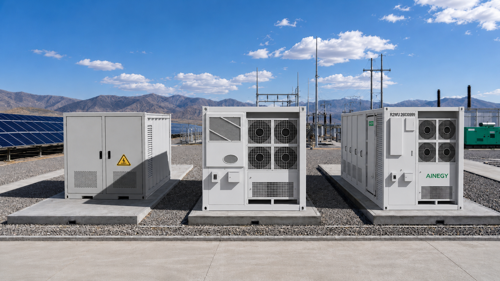
Configure Your 5MW/10–20MWh Grid-Connected BESS with AINEGY
Send the required MW power, MWh energy capacity, target storage duration, grid voltage, point-of-connection requirements, protection and metering requirements, communication protocol, operating strategy, ambient conditions and site layout. AINEGY will review the 10MWh or 20MWh battery configuration, 5MW PCS platform, 5500kVA transformer matching, EMS integration and multi-unit expansion requirements.