
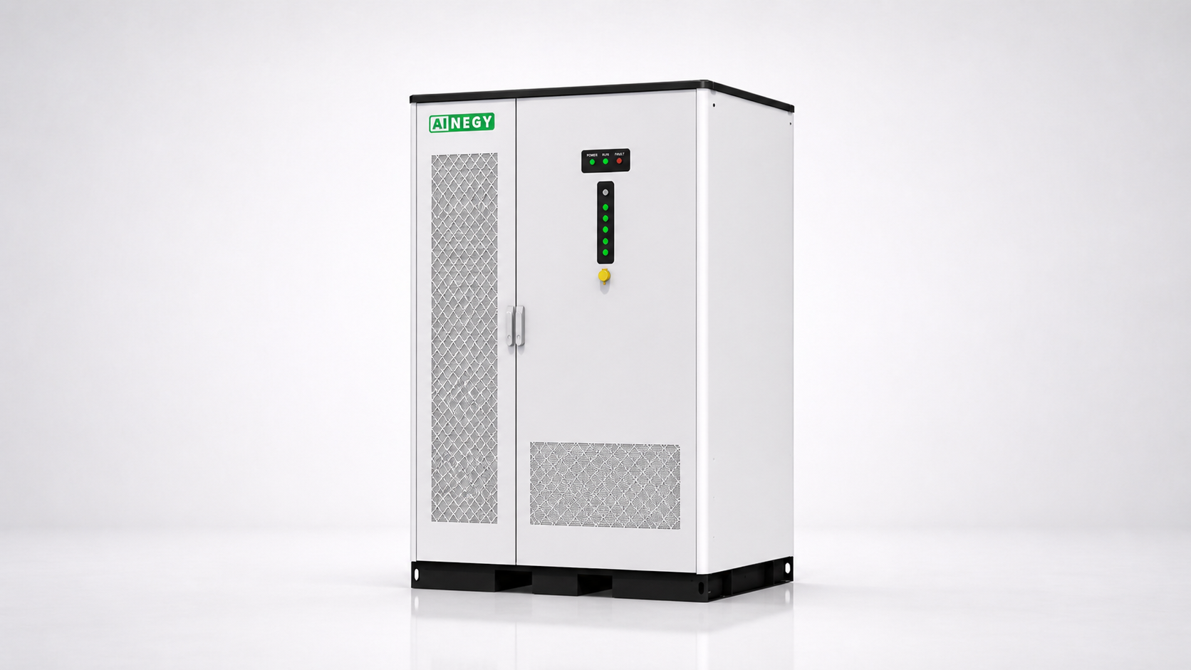
AINEGY High-Power Solar Diesel Hybrid Microgrid BESS Cabinet / Liquid Cooling
A high-power liquid-cooled microgrid BESS cabinet for C&I projects that need stronger PCS output, PV-battery-diesel coordination, fast source switching and engineered critical-load support.
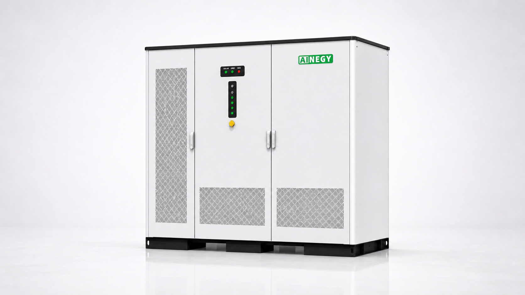
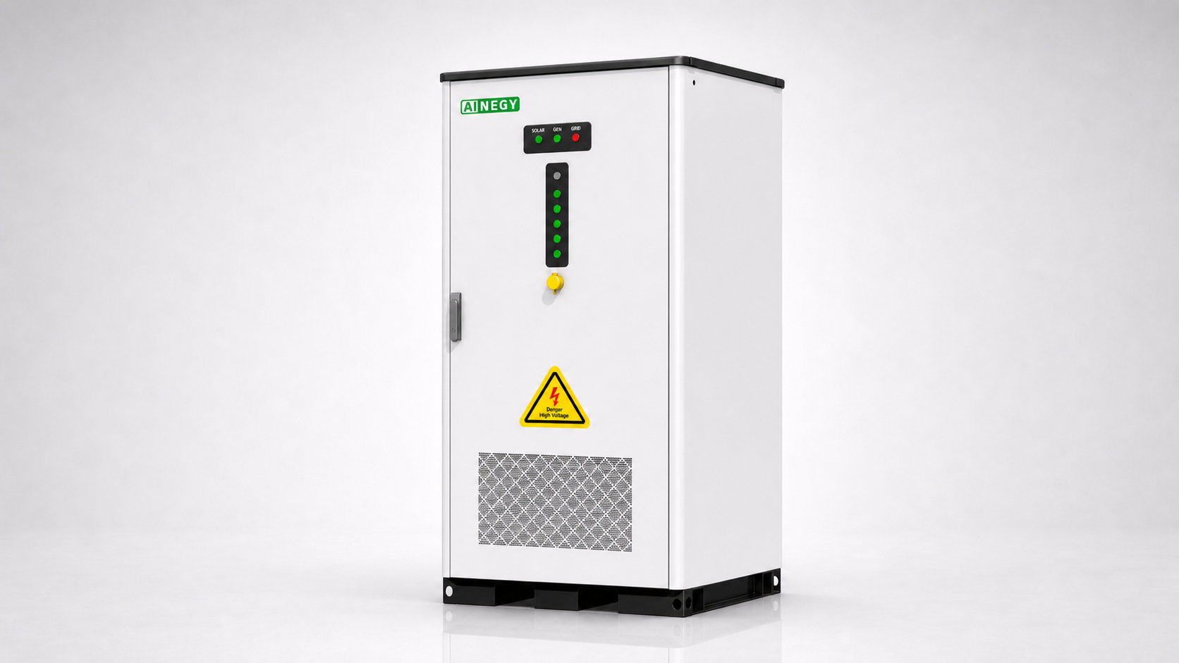
The AINEGY 250kW/261kWh high-power platform integrates LiFePO4 battery storage, BMS, PCS, EMS, PV MPPT input, diesel generator interface, fire protection and communication architecture inside one cabinet. It is designed for factories, gas stations, supermarkets, PV power supply, remote sites and C&I microgrids where the power demand is higher than a standard 125kW cabinet can support.
What Makes It a High-Power AINEGY Microgrid BESS Cabinet?
This page is for the 250kW/261kWh high-power configuration. It is not positioned as a long-duration battery cabinet. Its main value is stronger PCS output and higher AC current capability for C&I microgrid projects where instantaneous power demand, motor loads, pumps, compressors or critical-load buses exceed the range of a standard 125kW cabinet.
The 250kW/261kWh model is selected for power demand. It is not the same positioning as a long-duration 250kW/522kWh configuration.
High Power Does Not Mean Long Duration
Professional buyers often confuse output power with backup duration. For this page, the key selling point is stronger 250kW PCS capability with a compact 261kWh liquid-cooled battery system. This is valuable for sites with higher instantaneous load demand, but backup duration still depends on usable battery energy, SOC reserve, actual load level, PV availability and generator support.
AINEGY Energy Coordination Logic for High-Power Hybrid Microgrids
A 250kW solar diesel hybrid ESS creates value when its high-power PCS, PV input, battery reserve, generator support and critical-load bus are dispatched as one engineered microgrid system.
Serve Stronger C&I Load Buses
The 250kW platform is intended for sites where critical loads, pumps, process equipment or commercial backup buses require stronger output than a standard-power cabinet.
Use Available PV Before Fuel-Based Generation
Available solar energy can supply local demand or charge the battery, helping the project improve onsite renewable-energy utilization.
Reduce Short-Duration Generator Cycling
Battery discharge can buffer short peaks, PV fluctuation and temporary load changes, reducing unnecessary generator response in properly configured projects.
Support Sustained High Load or Low Solar Periods
Diesel generator support can be used when PV production and stored battery energy are insufficient for sustained demand.
Keep Energy Available for Priority Loads
EMS strategy can maintain a defined battery reserve so operational optimization does not consume the energy allocated to critical-load support.
Scale High-Power Microgrid Capacity
Up to 6 cabinets can be engineered in parallel, subject to synchronized control, AC bus design, protection coordination and commissioning.
AINEGY Engineering Behind the 250kW/261kWh High-Power Cabinet
Product value is supported by battery protection, high-power conversion, EMS dispatch, thermal control, field visibility and manufacturing experience—not by rated power alone.
Years of BMS/EMS Technology Accumulation
AINEGY’s energy-storage platform is built around long-term development of battery-management and energy-management technologies.
Countries and Regions Reached
International project exposure supports adaptation to different grid, generator, voltage and environmental conditions.
Energy Storage Product Models
A broad product platform supports cabinet, container, residential and project-specific energy storage configurations.
Cumulative Battery Shipment
Manufacturing and delivery experience supports repeatable battery-system integration and international project execution.
Battery State Estimation and Multi-Layer Protection
The BMS platform supports cell monitoring, balancing, temperature and current supervision, SOC estimation, hierarchical management and coordinated fault response.
250kW Microgrid Power Conversion
The 250kW PCS platform is selected for C&I microgrid projects requiring stronger output power and higher AC current capability.
Multi-Source Operating Strategy
EMS provides the control layer for PV priority, battery SOC reserve, generator-assisted operation, grid/island modes and multi-unit coordination.
Thermal Support for a Compact 261kWh Cabinet
Liquid cooling supports module temperature consistency and thermal behavior in a compact high-energy-density cabinet under variable C&I duty cycles.
Battery Protection, Fire Protection and Electrical Coordination
Battery-side IP65 protection, integrated fire protection and BMS/PCS fault coordination create multiple protection layers for project operation.
RS485, Ethernet and 4G Communication
Multiple communication interfaces support local integration, remote operating visibility and connection to the wider monitoring architecture.
High-Power Microgrid Status Made Visible in the Field
AINEGY T-Visual™ converts hybrid-energy operation into an immediate front-panel status language. Operators can identify solar, grid and generator source status, system run or fault condition and battery energy level without first navigating a multi-page monitoring interface.
Model Selection: 120kW PV Input or 240kW PV Input
The high-power 250kW/261kWh platform is available with two PV input configurations. Selection should be based on PV array size, daytime load profile, solar resource, battery charging target and diesel generator operating strategy.
| Configuration | 120kW PV Input Version | 240kW PV Input Version |
|---|---|---|
| Model | IYP-B261L-250H3S-120M1-HX1 | IYP-B261L-250H3S-240M2-HX1 |
| Best Fit | Projects with moderate PV capacity, limited array space or lower daytime solar charging target. | Projects with larger PV array area, stronger daytime solar resource or higher PV self-consumption target. |
| Battery Energy | 261kWh | 261kWh |
| PCS Platform | 250kW high-power platform | 250kW high-power platform |
| PV Input | 120kW, 1 channel | 240kW, 2 channels |
| Max. PV Voltage | 950Vdc | 950Vdc |
| MPPT Range | 250–850Vdc | 250–850Vdc |
| Max. PV Input Current | 200A | 200A + 200A |
| Approximate Weight | About 2500kg | About 2550kg |
Balanced High-Power Microgrid Cabinet
Suitable when the project requires 250kW PCS output but the available PV capacity or installation area does not justify a 240kW PV input configuration.
Higher Solar Input for Daytime Energy Use
Suitable when the project has stronger PV generation potential and wants to increase daytime charging and solar self-consumption.
PV Sizing Must Match Load and SOC Strategy
Final PV selection should use hourly load data, solar generation estimates, generator strategy and required battery SOC reserve.
Advantages of AINEGY Liquid Cooling for a High-Power 261kWh BESS Cabinet
For a compact 261kWh cabinet with a 250kW PCS platform, thermal management is not only about reducing maximum temperature. AINEGY liquid cooling is designed to improve heat-transfer efficiency, support module temperature consistency and reduce dependence on long cabinet airflow paths during high-power discharge, PV charging and generator-assisted recharge.
| Engineering Consideration | Air-Cooled Cabinet | AINEGY Liquid-Cooled High-Power 261kWh Cabinet |
|---|---|---|
| Heat-transfer path | Uses conditioned airflow and cabinet air ducts to remove heat. | Uses circulating coolant and cold-plate paths positioned closer to battery-module heat sources. |
| Temperature uniformity | Depends strongly on airflow balance, filter condition, duct resistance and cabinet layout. | Better suited to controlling module-to-module temperature variation in a compact high-energy-density arrangement. |
| High-power duty | Suitable where discharge intensity, charge rate and ambient stress are moderate. | More appropriate for 250kW high-power microgrid operation with changing charge, discharge and generator-assisted recharge cycles. |
| Cabinet energy density | Requires adequate air channels and heat-exchange space around battery racks. | Supports a denser 261kWh cabinet architecture without relying only on large internal airflow passages. |
| Project economics | Lower initial complexity and cost; suitable for lower-duty or budget-sensitive projects. | Higher thermal-system complexity, justified where high-power operation, compactness and thermal consistency have higher project value. |
Thermal Consistency Matters
High-power stationary BESS operation requires attention to module temperature consistency, not only the hottest single point.
Reduced Dependence on Airflow Paths
Liquid cooling reduces reliance on long airflow channels through a densely populated cabinet, where resistance and recirculation can create uneven conditions.
Designed for C&I Microgrid Duty
The thermal architecture supports changing heat loads caused by PV charging, 250kW discharge, generator-assisted recharge and outdoor site conditions.
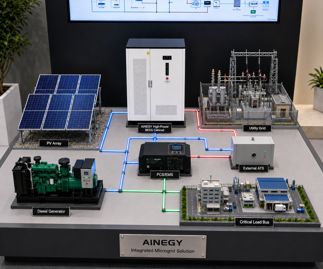
AINEGY High-Power PV–Battery–Grid–Diesel Microgrid Architecture
The system architecture connects PV generation, battery storage, PCS output, EMS dispatch, utility grid, diesel generator, external ATS and critical loads. The AINEGY high-power cabinet supplies the storage, conversion, solar-input and control core, while the project switchgear defines source isolation, protection and load distribution.
Problems the AINEGY High-Power Microgrid BESS Cabinet Helps Solve
The AINEGY 250kW/261kWh liquid-cooled high-power microgrid BESS cabinet is designed for C&I and remote power projects where stronger PCS output, PV generation, battery storage, grid supply, diesel generator backup and critical loads must be coordinated in one system.
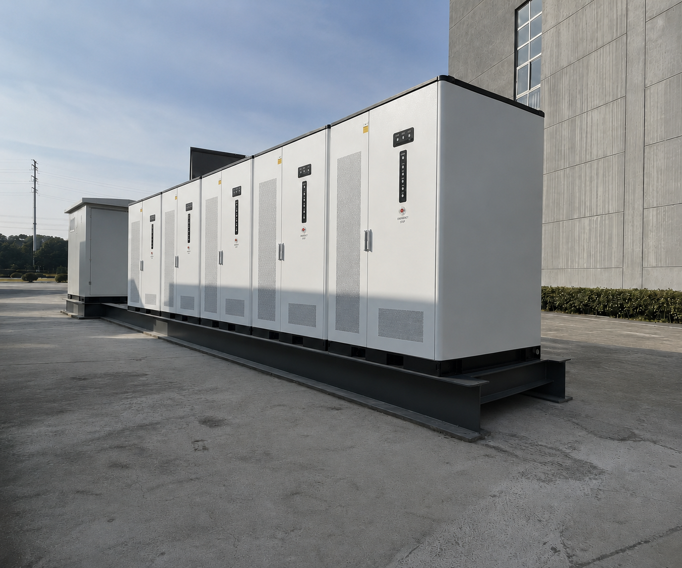
From High-Power Load Problem to Microgrid Configuration
AINEGY helps project owners and EPCs move from a simple equipment purchase to a complete high-power microgrid configuration logic: PCS output, PV capacity, generator power, battery reserve, critical-load duration, motor starting demand, ATS topology, site temperature, communication and future expansion are evaluated together.
Support Stronger C&I Power Demand
AINEGY high-power configuration considers motors, compressors, pumps, power factor, peak demand and phase balance instead of relying only on nominal running power.
Protect Larger Priority Load Buses
AINEGY microgrid design supports selected loads such as pumps, refrigeration, lighting, POS, communication and control systems during grid instability or outages.
Coordinate PV, Battery and Diesel Support
AINEGY high-power microgrid BESS stores solar energy, buffers PV fluctuation and coordinates generator support for remote projects where fuel cost and power reliability matter.
AINEGY 250kW/261kWh High-Power Technical Specifications
The high-power platform combines a 261kWh high-voltage LiFePO4 battery system, 250kW PCS architecture and selectable 120kW or 240kW PV input within a liquid-cooled cabinet.
| Item | 120kW PV Input Version | 240kW PV Input Version |
|---|---|---|
| Product | AINEGY High-Power Solar Diesel Hybrid Microgrid BESS Cabinet / Liquid Cooling | AINEGY High-Power Solar Diesel Hybrid Microgrid BESS Cabinet / Liquid Cooling |
| Model | IYP-B261L-250H3S-120M1-HX1 | IYP-B261L-250H3S-240M2-HX1 |
| Battery System | ||
| Battery Chemistry | LiFePO4 | LiFePO4 |
| Rated Energy | 261kWh | 261kWh |
| Nominal Voltage | 832V | 832V |
| Rated Capacity | 314Ah | 314Ah |
| Battery Cooling | Liquid cooling | Liquid cooling |
| PV Input | ||
| Maximum PV Power | 120kW, 1 channel | 240kW, 2 channels |
| Maximum PV Voltage | 950Vdc | 950Vdc |
| MPPT Voltage Range | 250–850Vdc | 250–850Vdc |
| Maximum PV Input Current | 200A | 200A + 200A |
| MPPT Channels | 1 | 2 |
| AC On-grid | ||
| Rated Power | 250kW / 1min, 200kW / 3min, 175kW / 5min | 250kW / 1min, 200kW / 3min, 175kW / 5min |
| AC Voltage | 400Vac / 230Vac, L1 / L2 / L3 / N / PE | 400Vac / 230Vac, L1 / L2 / L3 / N / PE |
| Rated Frequency | 50Hz / 60Hz | 50Hz / 60Hz |
| Maximum AC Current | 375A / 1min, 300A / 3min, 265A / 5min | 375A / 1min, 300A / 3min, 265A / 5min |
| AC Off-grid | ||
| Rated Power | 250kW | 250kW |
| AC Voltage | 400Vac / 230Vac, L1 / L2 / L3 / N / PE | 400Vac / 230Vac, L1 / L2 / L3 / N / PE |
| Rated Frequency | 50Hz / 60Hz | 50Hz / 60Hz |
| Maximum AC Current | 375A | 375A |
| On/Off-grid Switching Time | <20ms | <20ms |
| Maximum Parallel Quantity | 6 units | 6 units |
| Microgrid Interfaces and General Data | ||
| ATS Transfer Architecture | External ATS compatible | External ATS compatible |
| Diesel Generator Interface | Yes | Yes |
| Communication | RS485 / Ethernet / 4G | RS485 / Ethernet / 4G |
| Battery Protection Rating | IP65 | IP65 |
| Fire Protection System | Yes | Yes |
| Operating Temperature | -10°C to 55°C | -10°C to 55°C |
| Relative Humidity | 5% to 95% | 5% to 95% |
| Altitude | <2000m | <2000m |
| PCS Cooling | Intelligent cooling | Intelligent cooling |
| Dimensions | 1620 × 1300 × 2000mm | 1620 × 1300 × 2000mm |
| Approximate Weight | About 2500kg | About 2550kg |
High-Power Load Data Required
- Hourly load curve and maximum simultaneous demand
- Motor, pump and compressor starting current
- Power factor and reactive-power demand
- Critical and non-critical load separation
PV Array Data Required
- 120kW or 240kW PV configuration target
- Module Voc and temperature coefficient
- String operating voltage
- Maximum input current within MPPT limits
Generator and ATS Data
- Generator rated and standby power
- Minimum stable generator loading
- ATS current rating and transfer sequence
- Controller communication or start-stop interface
Parallel Project Data
- Required total PCS power
- AC bus and breaker design
- Protection selectivity and cable impedance
- EMS communication and commissioning sequence
Engineering FAQ and RFQ Readiness
These answers help EPCs, distributors and C&I project owners prepare accurate technical requirements before requesting an AINEGY high-power microgrid quotation.
The main difference is power capability. This page uses a 250kW PCS platform for stronger C&I load demand, while the 125kW/261kWh cabinet is more suitable for projects with lower instantaneous output requirements.
The off-grid rated power is 250kW. The on-grid power rating is specified as 250kW for 1 minute, 200kW for 3 minutes and 175kW for 5 minutes. Final selection should consider operating mode, site temperature and load profile.
Choose 120kW PV input when the available PV array is smaller, installation space is limited or the project mainly needs high-power storage output rather than high solar charging capacity.
Choose 240kW PV input when the site has stronger daytime solar generation, larger PV array area or a higher target for solar self-consumption and battery charging.
261kWh with 250kW output is a high-power configuration, not a long-duration configuration. Backup duration depends on actual load, usable battery energy, SOC reserve, PV availability and generator support. For longer autonomy, evaluate the 250kW/522kWh model.
Motor starting must be checked before selection. Provide locked-rotor current, starting duration, soft-start or VFD information, power factor, simultaneous starting sequence and acceptable voltage deviation.
Parallel projects require synchronized PCS control, EMS communication, AC bus and breaker sizing, protection selectivity, cable-impedance review, SOC alignment and a controlled commissioning sequence.
Send the single-line diagram, PV module and string data, generator specification, hourly load profile, motor-starting information, critical-load list, backup-duration target, ambient temperature, altitude, ATS requirement, communication protocol and expected expansion plan.
Configure Your High-Power Microgrid Project with AINEGY
Send your PV data, generator specification, load curve, motor-starting data, critical-load list, ATS topology, required backup duration and site conditions. AINEGY will use these inputs to evaluate 120kW or 240kW PV input, 250kW PCS output, battery reserve, generator coordination and parallel expansion requirements.