Limited Transformer or PCC Power
The planned charging output is higher than the continuous power available from the transformer or utility connection.

AINEGY integrates DC fast charging, LiFePO4 battery storage, optional solar PV and site-level energy management across 80–480 kW charging platforms with 87 kWh to 1.5 MWh of battery capacity.
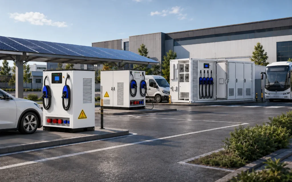 Grid + PV + BESS + DC Fast Charging
Battery-buffered EV charging combines stationary battery storage, DC charging power modules and site-level controls. The grid and optional solar PV replenish the BESS at a controlled rate, while the BESS supplies additional power when connected vehicles request more charging power than the grid connection can continuously provide.
The solution is most useful when charging demand, grid capacity, solar generation, tariffs or vehicle schedules create a measurable power or energy mismatch.
The planned charging output is higher than the continuous power available from the transformer or utility connection.
Vehicles create short-duration charging peaks rather than drawing the station's maximum output continuously.
Transformer, cabling, medium-voltage equipment or utility upgrades would add cost and delay deployment.
Monthly maximum demand or time-of-use electricity prices materially affect charging-station operating cost.
Solar generation can supply vehicles, charge the BESS or support site loads when coordinated through the selected architecture.
Fleet schedules allow the EMS to prioritize vehicles by departure time, required SOC and available charging window.
EV charging shares transformer capacity with factory, warehouse, workshop, office or other industrial loads.
The site requires higher short-duration charging power than its weak or constrained power source can directly deliver.
Charger nameplate power, vehicle demand, site energy and grid capacity are different design variables. A professional assessment must model all four.
The charger may be rated above the power that the grid, PV and BESS can sustain over a long charging period.
Concurrent sessions create a higher station peak, but each vehicle follows a different charging curve and acceptance limit.
Vehicle SOC, battery temperature, voltage and onboard controls determine the actual power requested from the charger.
Transformer, cable and utility limits may require the EMS to cap grid import while the BESS supports charging peaks.
A BESS with sufficient discharge power can still become energy-limited during repeated or extended charging sessions.
A brief high grid-import event may establish the billing demand for an entire month under applicable tariffs.
First-hour performance does not guarantee design-day performance if daily grid and PV energy cannot replace discharged energy.
Grid supply, switchgear, BESS, power modules, connectors, vehicle communication, CSMS and network services all affect successful charging.
AINEGY's three product platforms use different power-to-energy ratios, charging outputs and PV integration methods. They should not be represented by one universal system diagram.
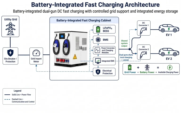
A compact 1C platform uses controlled grid input and integrated battery storage to support 80–240 kW DC fast charging through two charging guns.
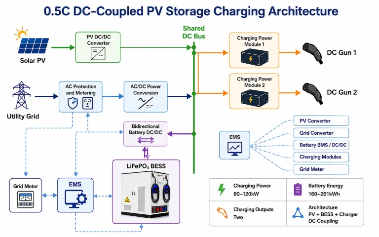
A 0.5C product family coordinates solar PV, grid energy, battery storage and 80–120 kW DC charging through a shared DC-coupled architecture.
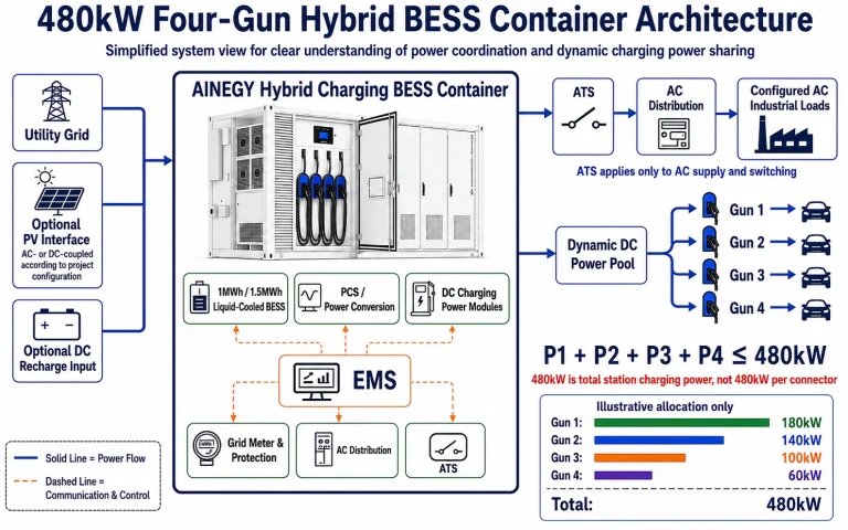
A station-level system combines 480 kW of total DC charging power with four dynamically managed guns and 1 MWh or 1.5 MWh liquid-cooled storage.
Select the product family according to charging power, battery duration, grid capacity, PV integration and vehicle operating profile. Final model data should be confirmed from the applicable datasheet.
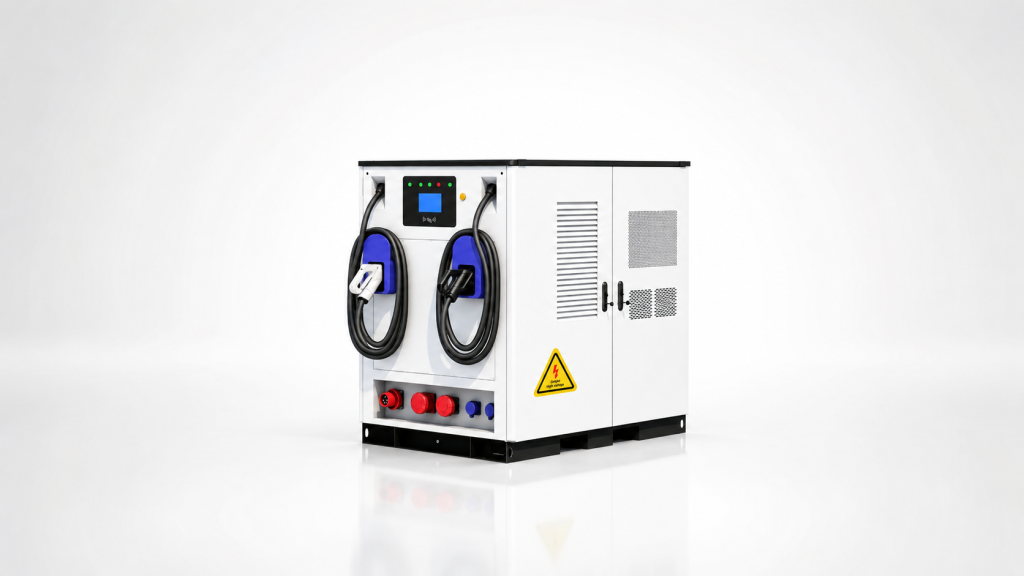
80–240 kW DC fast charging with 87–265 kWh LiFePO4 storage, dual charging guns, a 1C battery platform and integrated EMS.
View Product Details →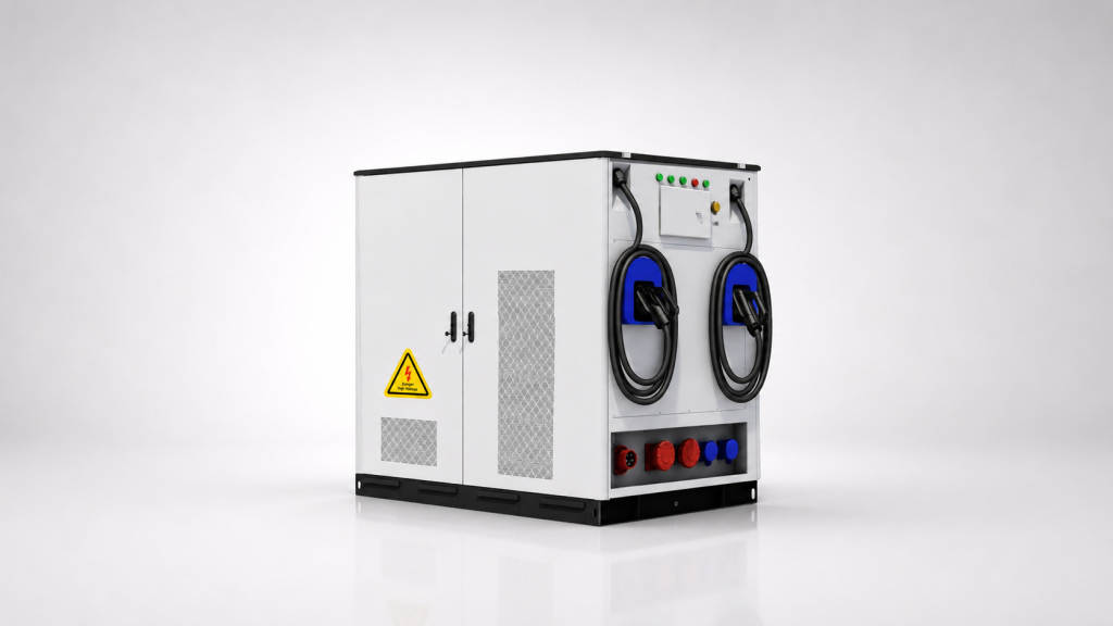
80–120 kW DC charging with 160–261 kWh LiFePO4 storage, two charging guns and PV, BESS and charger DC coupling.
View Product Details →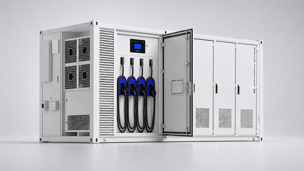
480 kW of total dynamically allocated charging power with four guns, 1 MWh or 1.5 MWh liquid-cooled storage, integrated EMS and ATS.
View Product Details →Confirmed data is stated directly. Functions that depend on a model, market or project configuration are labelled accordingly rather than assumed.
| Capability | Battery-Integrated Fast Charging | 0.5C DC-Coupled PV Charging Cabinet | 480 kW Hybrid BESS Container |
|---|---|---|---|
| DC Charging Power | 80 / 120 / 160 / 240 kW | 80 / 120 kW | 480 kW Total |
| Battery Energy | 87 / 122 / 162 / 265 kWh | 160 / 209 / 261 kWh | 1 MWh / 1.5 MWh |
| Product Form | Integrated Cabinet | Integrated Cabinet | Container / Integrated Cabin |
| Charging Guns | Two | Two | Four |
| Simultaneous Charging | Yes | Yes | Yes |
| Battery Platform | 1C | 0.5C Family | Confirm by Datasheet |
| PV Integration | By Model | DC Coupled | Optional |
| Grid Input | Yes | Yes | Yes |
| Optional DC Recharge Input | Confirm by Model | By DC Architecture | Optional |
| AC Industrial Load Output | Confirm by Model | Confirm by Model | Configured Option |
| Integrated EMS | Yes | Confirm by Datasheet | Yes |
| Integrated ATS | Confirm by Model | Confirm by Model | Yes |
| Cooling | Air / Liquid | Air / Liquid | Liquid |
| Connector Standard | GB/T / CCS / CHAdeMO | Confirm by Model | By Market / Model |
| Best Fit | Compact high-power battery buffering | PV utilization and longer buffering | High-power hubs, fleets and shared AC loads |
The correct platform is determined by the required station power, energy duration, solar architecture, number of charging guns and site-level operating objectives.
Use this platform when compact equipment and higher charging power relative to battery capacity are the main priorities.
Use this platform when solar utilization and longer energy buffering are more important than the highest charging power.
Use this platform for station-level charging hubs requiring four guns, MWh-scale storage and coordination with additional site loads.
The 480 kW rating is the total charging power available to the complete four-gun system. It is dynamically allocated among connected vehicles according to vehicle demand, gun limits, system power, BESS SOC and the EMS strategy. It is not 480 kW per gun.
All active charging guns draw from a common station power limit.
The assigned charging power is limited by the most restrictive real-time condition.
The EMS continuously balances charging requests, grid-import limits, PV production, battery conditions, tariffs and any configured AC facility loads.
The grid supplies the site and replenishes the BESS without exceeding the configured transformer or PCC limit.
The BESS supplies the power difference when EV charging demand is greater than the available grid and PV power.
Charging power is assigned to active guns according to vehicle requests, system limits and operational priority.
Available PV can supply charging, facility loads or BESS charging according to the selected DC- or AC-coupled strategy.
Configured industrial loads are monitored so EV charging and facility demand remain within system and grid limits.
BESS dispatch is controlled around a defined maximum grid-import target at the point of connection.
The BESS can replenish during approved lower-cost periods while preserving sufficient capacity for future sessions.
When stored energy is insufficient, charging power is reduced to a level supported by the grid, PV and configured reserve.
Charging or AC-load support during a grid outage is available only when the ATS, power conversion and controls are designed for that mode.
The system must satisfy instantaneous power and cumulative energy requirements. Charging-station nameplate power alone cannot determine the correct battery or grid capacity.
Battery power covers the short-duration deficit between all site loads and the available external power sources.
Usable battery energy is based on the maximum cumulative energy deficit during the design charging period.
Nameplate capacity must be higher than the required delivered energy because not all stored energy is available throughout project life.
The grid input must support design-day energy and restore BESS SOC before the next required charging period.
First-Hour analysis checks whether the station can serve a sudden high-demand period. Design-Day analysis checks whether the grid, PV and BESS can meet the intended busy-day energy requirement without depleting the battery.
Evaluate the maximum charging and AC-load energy requested during the first hour after vehicles arrive.
Confirm that the busiest intended day can be served without persistent SOC depletion or unmanaged charging curtailment.
Vehicle charging communication, charging-network management and site energy management are separate control layers. Product compatibility must be confirmed for the selected charging standard and market.
Controls the charging session and vehicle power request.
Supports network operations, authorization and remote charging management.
Coordinates grid, PV, BESS, charging guns and configured AC loads.
The business case must compare avoided electrical upgrades and operating savings with the added cost, losses, degradation, controls and maintenance of the BESS.
NREL reports that appropriately sized battery-buffered systems can reduce required grid-service capacity by approximately 50%–80% compared with an entirely grid-powered station under the study's stated assumptions.
Research benchmark, not a universal project guarantee.The battery must support the intended sudden charging demand after subtracting the energy supplied by the grid and other sources during the same period.
Use project vehicle and charging data.The selected grid connection and BESS must meet the busy-day charging requirement without persistent depletion or unacceptable power curtailment.
Use the intended future utilization year and percentile day.No fixed payback period should be published without station utilization, charging price, tariff, demand charge, grid-upgrade quotation, battery cycling and project-cost assumptions.
Reliable charging depends on the complete power, communication and service chain. A BESS can provide short-duration energy support, but outage charging requires compatible hardware, software, isolation and control.
Grid, PV and BESS resources can meet the current charging request while respecting system limits.
Charging power is reduced when BESS power, energy or availability is insufficient for the requested station output.
The EMS preserves battery SOC for priority vehicles, configured AC loads or a defined short-duration contingency.
Selected loads continue only when the ATS, PCS, protection and control architecture were designed and tested for grid interruption.
Applicable certifications and standards depend on the selected product, connector configuration, installation country and local authority requirements. The page should not claim worldwide certification without model-specific evidence.
Confirm the applicable EVSE and charging-system requirements for the destination market.
Battery and complete-system requirements must match the selected BESS and installation.
Compatibility is confirmed by product model and market rather than inferred from the protocol name.
Projects capable of exporting or operating as an energy-storage DER require utility and market-specific review.
Cooling, detection, suppression, spacing and emergency access are selected for the product and site.
Commissioning should verify normal, constrained and fault operating states.
Each charging scenario has a different concurrency pattern, energy requirement, business model and grid constraint.
Random vehicle arrivals require First-Hour analysis and future Design-Day utilization forecasts.
Key inputs: sessions, energy per session and grid limit.Low average utilization can coexist with sudden multi-vehicle demand during travel peaks.
Key inputs: surge demand, uptime and recovery energy.Existing electrical capacity, installation space and deployment schedule often constrain charger expansion.
Key inputs: transformer capacity, civil works and tariff.Known arrival and departure schedules support priority charging and controlled grid demand.
Key inputs: route energy, dwell time and departure SOC.Concentrated return-to-base charging requires schedule, concurrency and daily energy analysis.
Key inputs: fleet timetable, bus battery and charging window.Vehicle charging competes with production and building loads for transformer capacity.
Key inputs: existing AC load and expansion plan.Operational vehicles have time-sensitive charging requirements and may share power with industrial equipment.
Key inputs: duty cycle, vehicle priority and site loads.Available grid or local generation must be checked against repeated charging energy, not only peak power.
Key inputs: source energy, BESS recovery and reserve.These examples demonstrate calculation logic. They are not final equipment selections or guaranteed project outcomes.
A grid-constrained commercial site requires dual-gun fast charging without an MWh-scale BESS.
Select the model from the actual grid-power deficit, concurrency, session duration and battery recovery time.
A solar-equipped site requires longer buffering and direct coordination of PV, BESS and EV charging.
Final analysis requires the hourly PV profile, charging schedule, grid contribution and permitted solar curtailment.
A four-gun site uses MWh-scale storage and dynamic power sharing under a defined grid-import limit.
First-Hour demand, Design-Day energy, AC facility loads and BESS recharge time determine the applicable configuration.
Charging demand must be described as vehicle events over time, not only as a desired charger nameplate rating.
The delivery process should validate power allocation, daily energy balance, communications and constrained operating modes before commercial operation.
Confirm vehicles, charging service, business model and site operating targets.
Check transformer, PCC, electrical infrastructure and existing AC demand.
Build arrival, departure, SOC, session-energy and concurrency profiles.
Calculate sudden high-demand power and energy requirements.
Confirm daily energy input, battery recovery and intended uptime.
Choose the 1C cabinet, DC-coupled cabinet or 480 kW container.
Configure grid, PV, BESS, EV charging, ATS and AC-load interfaces.
Verify connectors, protocols, market standards and back-office integration.
Compare grid upgrades, tariffs, degradation, CAPEX and charging revenue.
Complete agreed charging, BESS, EMS, ATS and communication tests.
Verify grid import, dynamic allocation, charging sessions and protection.
Confirm low-SOC derating, equipment alarms and outage operation where configured.
Document charging priorities, monitoring, alarms and emergency actions.
Compare actual utilization, grid import and energy delivery with the design model.
A complete case study should identify the site type, grid capacity, AC load, charging power, number of guns, BESS power and energy, PV capacity, baseline period, measurement period, maximum grid import, sessions completed, energy delivered and any verified grid-upgrade or demand-cost result.
View EV Charging Case StudiesDirect answers to product, sizing, charging-power and project-development questions.
It uses stationary battery storage to supply short-duration charging power above the continuous power available from the grid, while the grid and optional PV replenish the battery over time.
AINEGY currently presents three product platforms: a 1C battery-integrated fast charging system, a 0.5C DC-coupled PV storage charging cabinet and a 480 kW four-gun hybrid BESS container.
The confirmed product range covers 80–480 kW of total DC charging power, depending on the selected cabinet or container platform.
The confirmed portfolio covers 87 kWh to 1.5 MWh, including compact cabinet configurations and 1 MWh or 1.5 MWh container options.
No. The 480 kW rating is the total charging power of the four-gun system. The sum of the power assigned to all active guns must remain at or below 480 kW.
Yes. Four vehicles can be connected simultaneously to the 480 kW system, with available power allocated among them according to demand and system limits.
Not necessarily. Power can be distributed unequally according to each vehicle's request, connector limits, priority, BESS condition and available station power.
It is a 1C integrated cabinet family offering 80–240 kW DC charging, 87–265 kWh LiFePO4 storage, two charging guns and integrated EMS.
It is an 80–120 kW dual-gun charging cabinet with 160–261 kWh storage and a DC-coupled architecture for PV, battery storage and EV charging.
Both are options for the 480 kW four-gun platform. The 1.5 MWh version provides more energy duration, reserve and design-day buffering, subject to the same project-specific power and control limits.
A fixed vehicle count cannot be determined from nameplate capacity alone. It depends on usable battery energy, energy per vehicle, grid and PV contribution, AC loads, losses and required reserve.
The system should enter a defined degraded mode, usually reducing charging power to a level supported by the grid, PV and remaining reserve rather than continuing unsustainable full-power output.
Yes. Battery buffering can support charging power above the continuous grid limit for a defined duration, provided daily energy input and battery recovery are sufficient.
No. It may avoid or defer some upgrades, but the result depends on charging demand, available grid energy, BESS size, design-day utilization and the utility's interconnection requirements.
Yes. The 0.5C cabinet is designed around DC-coupled PV, storage and charging. Other platforms can use optional PV when the applicable product and project architecture support it.
The 480 kW hybrid BESS container can be configured with AC industrial-load output. The supported power, priority and outage mode must be defined for the project.
The ATS manages the configured AC source-transfer function. It does not by itself guarantee uninterrupted EV charging or full-power operation during a grid outage.
Only a system specifically configured with compatible isolation, ATS, power conversion, controls and sufficient battery energy can continue serving defined charging or AC loads during an outage.
It is based on EV charging demand plus simultaneous AC loads minus permitted grid import and available PV, with additional margin for efficiency, thermal limits and operating reserve.
It is based on the maximum cumulative energy deficit over the selected charging period, then adjusted for usable SOC, efficiency, end-of-life capacity and reserve.
First-Hour checks sudden charging demand. Design-Day checks whether the intended busy-day demand can be served without depleting the battery or unacceptable charging curtailment.
OCPP primarily connects the charging station with a charging-station management system. ISO 15118 defines high-level communication between the EV and EVSE. Support must be confirmed by product model.
The battery-integrated product family lists GB/T, CCS and CHAdeMO. Connector and communication support for other products must be confirmed by model and destination market.
Provide grid capacity, existing loads, vehicle types, charging events, energy per session, concurrency, arrival and departure times, PV data, connector standard, site conditions and the single-line diagram.
Primary research and standards sources supporting battery-buffered charging, economics, reliability, communications, safety and interconnection.
Battery-buffered charging, grid-capacity reduction, resilience, First-Hour and Design-Day criteria.
Open NREL Reference →Case-study analysis of battery-buffered options for a constrained charging location.
Open NREL Case Study →Economic analysis highlighting utilization, electricity price and demand charges.
Open NREL Research →Relationships among charging-station reliability, resilience, grid conditions and EV adoption.
Open NREL Research →Official information on OCPP versions for charging-station and CSMS communication.
Open OCPP Reference →Vehicle-to-grid communication-interface requirements between the EV and EVSE.
Open ISO Standard Page →Requirements for DC electric-vehicle supply equipment and energy transfer.
Open IEC Standard Page →Safety and performance context for EV charging equipment, personnel protection and connectors.
Open UL Reference →Guidance for interconnecting energy-storage distributed-energy resources with electric power systems.
Open IEEE Standard Page →Send your transformer capacity, permitted grid import, existing AC loads, vehicle schedule, energy per session, solar information, connector standard and operating objectives. AINEGY will evaluate the applicable charging platform, BESS power, battery capacity, grid input and control strategy.