
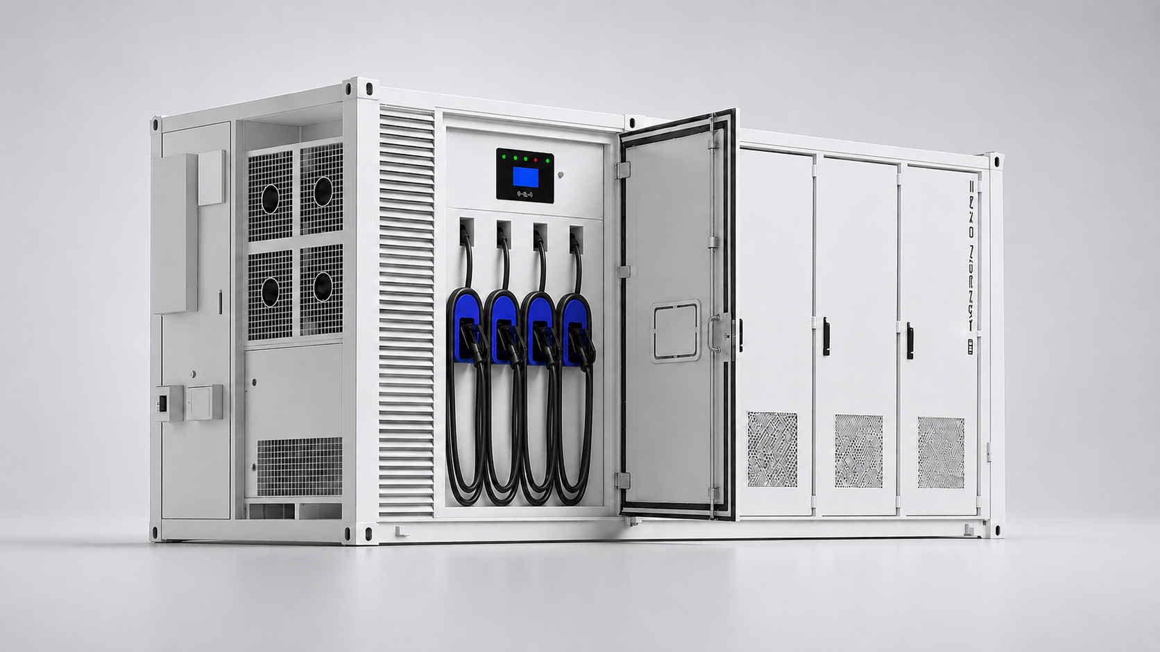
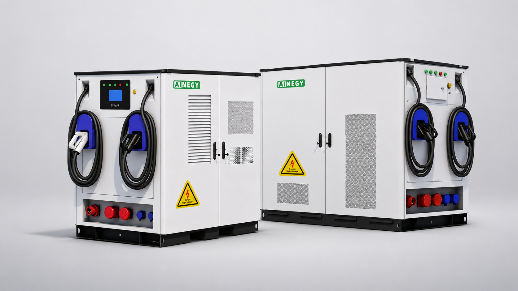
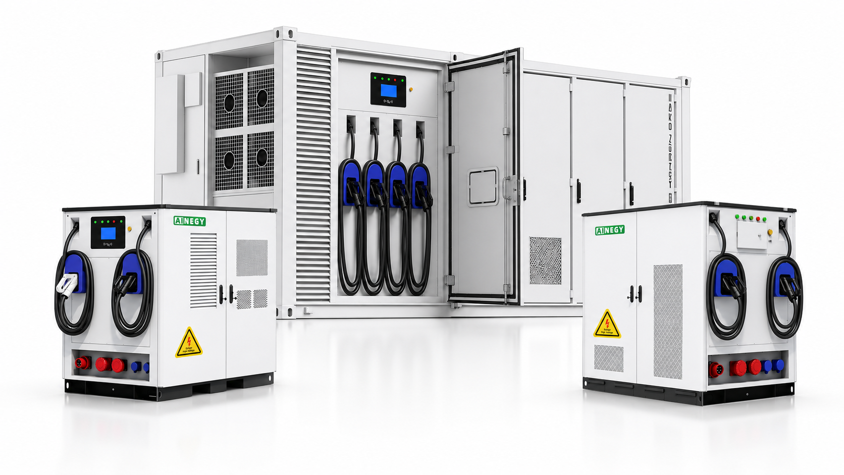
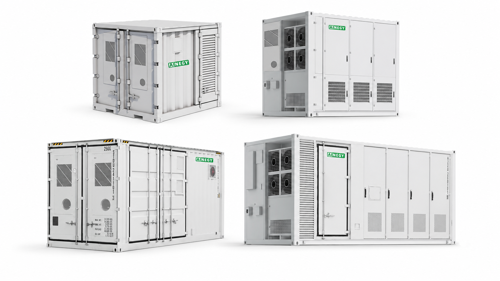
AINEGY 480kW Four-Gun EV Fast Charging Hybrid BESS Container
A large-capacity hybrid energy storage container built around 480kW four-gun EV fast charging, with simultaneous charging and intelligent allocation of the total charging capacity.
The AINEGY system combines 1MWh or 1.5MWh of liquid-cooled LiFePO4 battery storage with a 480kW EV fast charging platform. Integrated EMS and ATS coordinate grid power, battery energy, optional PV input, optional DC recharge, four active charging guns and additional AC load output inside one containerized hybrid energy system.
480kW EV Fast Charging Built into a Hybrid Energy Storage Container
This product is based on AINEGY hybrid-grid energy storage architecture, with the EV charging function integrated directly inside the container. The result is not a conventional charger placed beside a battery container, but one coordinated power system.
This product supports the wider DC-Coupled PV Storage Charging System product group and the PV Storage EV Charging Systems category.
Four Active Charging Interfaces Within One 480kW Platform
Four charging guns can operate simultaneously, while total charging capacity is dynamically allocated among active vehicles.
1–1.5MWh Local Energy Buffer
Large-capacity liquid-cooled battery storage separates stored energy capacity from the instantaneous charging demand of connected EVs.
Grid, PV, DC Recharge and Battery Coordination
The integrated system supports AC grid recharge, optional DC recharge and optional high-capacity PV input.
EV Charging Plus Additional AC Loads
EV charging is the primary application, with 500kW or 750kW off-grid AC output available for compatible connected loads.
AINEGY Engineering and Quality Support
A four-gun charging energy system requires coordinated engineering across battery management, energy management, transfer control, charging modules, thermal management, communication and connected load interfaces.
Years of BMS / EMS Technology Accumulation
Long-term development experience in battery-management and energy-management technologies.
R&D Team Members
Engineering support across BMS, EMS, power conversion, battery integration and customized energy systems.
Countries and Regions
International project experience across different charging interfaces, grids and environmental conditions.
Cumulative Battery Shipment
Manufacturing and battery-integration experience supporting international project execution.
Engineer the Complete Four-Gun Power Path
Charging modules, total charger power, vehicle voltage and simultaneous charging demand are treated as one coordinated system.
EMS and ATS Inside the Product Boundary
Battery, grid, PV, recharge interfaces, EV charging and AC output are coordinated within the integrated container.
Configure Around the Real Charging Site
Vehicle demand, grid availability, PV capacity, load requirements and site conditions should be reviewed before final configuration.
480kW Four-Gun EV Fast Charging BESS Container Technical Specifications
Both systems combine 480kW total EV charging power, four simultaneous charging interfaces, integrated EMS and ATS, liquid-cooled battery storage and multiple recharge paths.
| Item | 480kW / 1MWh | 480kW / 1.5MWh |
|---|---|---|
| Model | IYP-CB1ML-480C4-500H3-480M4-HX1 | IYP-CB1M5L-480C4-750H3-720M6-HX1 |
| Battery System | ||
| Battery Type | LiFePO4 Battery | LiFePO4 Battery |
| Rated Battery Energy | 1MWh | 1.5MWh |
| Battery Cooling Method | Liquid Cooling | Liquid Cooling |
| EV Fast DC Charging System | ||
| Total Maximum Charger Power | 480kW | 480kW |
| Charger Voltage Range | 200–1000Vdc | 200–1000Vdc |
| Maximum Charger Current | 480A | 480A |
| EV Charging Guns | 4 | 4 |
| Simultaneous EV Charging | Supported | Supported |
| Charging Power Allocation | Dynamic Allocation | Dynamic Allocation |
| Charging Gun Type | GBT; CCS1 / CCS2 / CHAdeMO Optional | GBT; CCS1 / CCS2 / CHAdeMO Optional |
| Charging Cable Length | 7 — confirm unit in final project specification | 7 — confirm unit in final project specification |
| Operation Mode | Standalone; OCPP 1.6J Optional | Standalone; OCPP 1.6J Optional |
| DC Recharge Port — Optional | ||
| Maximum DC Recharge Power | 320kW | 320kW |
| DC Recharge Ports | 1 | 1 |
| DC Recharge Socket Type | GBT; CCS1 / CCS2 / CHAdeMO Optional | GBT; CCS1 / CCS2 / CHAdeMO Optional |
| AC Recharge | ||
| Maximum AC Recharge Power | 500kW | 750kW |
| AC Type | 3-Phase 400Vac | 3-Phase 400Vac |
| PV Recharge — Optional | ||
| Maximum PV Power | 480kW | 720kW |
| Maximum PV Voltage | 900Vdc | 900Vdc |
| MPPT Voltage Range | 250–850Vdc | 250–850Vdc |
| MPPT Channels | 4 | 6 |
| Off-Grid AC Output | ||
| Maximum AC Output Power | 500kW | 750kW |
| AC Voltage | 400Vac / 230Vac, 3-Phase | 400Vac / 230Vac, 3-Phase |
| AC Frequency | 50Hz / 60Hz | 50Hz / 60Hz |
| Maximum AC Current | 750A | 1130A |
| Integrated Control and General Parameters | ||
| Energy Management System | Integrated AINEGY EMS | Integrated AINEGY EMS |
| Automatic Transfer Switch | Integrated ATS | Integrated ATS |
| Communication | RS485; WiFi / 4G Optional | RS485; WiFi / 4G Optional |
| Battery Protection Rating | IP65 | IP65 |
| Fire Protection System | Aerosol | Aerosol |
| Operating Temperature | -15°C to 50°C | -15°C to 50°C |
| Operating Humidity | 5%–95% | 5%–95% |
| Altitude | <2000m | <2000m |
| Dimensions | 6058 × 2438 × 2896mm | 6058 × 2438 × 2896mm |
| Approximate Weight | About 22000kg | About 25000kg |
EV Charging Data
- Expected vehicle types
- Daily charging sessions
- Four-gun simultaneous charging demand
- GBT / CCS1 / CCS2 / CHAdeMO requirement
Site Energy Data
- Available grid power
- Grid voltage and site distribution
- Existing transformer capacity
- Additional connected load demand
PV and DC Recharge
- PV array capacity and string data
- Expected solar production
- External DC recharge source
- Required DC recharge connector
Control and Communication
- Charging power allocation strategy
- OCPP 1.6J requirement
- Remote communication requirement
- Grid and off-grid operating strategy
Four-Gun Simultaneous EV Charging with Dynamic Power Allocation
The charging system provides 480kW of total charging capacity. Four charging guns can operate simultaneously, while integrated control allocates available power among active vehicles instead of assuming a fixed equal output for every charging session.
Match Charging Power to Real Vehicle Demand
Connected vehicles can request different charging power according to battery voltage, SOC, onboard charging limits and current charging conditions. Dynamic allocation allows the system to coordinate the shared 480kW platform around active sessions.
1–1.5MWh Liquid-Cooled Battery Energy Behind 480kW EV Charging
The stationary battery is a core part of the charging architecture. It creates a large local energy buffer between available recharge sources and the changing power demand of four simultaneous EV charging sessions.
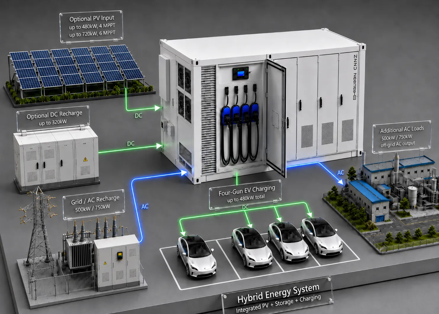
DC-Coupled PV-Storage Charging Inside One Hybrid Energy System
The system combines several energy inputs and outputs inside one product boundary. Optional PV input and the optional DC recharge port connect through DC energy paths, while grid AC recharge, ATS operation and additional AC output form the AC-side architecture.
Integrated AINEGY EMS and ATS for Hybrid Charging Energy Coordination
EMS and ATS are integrated inside the product rather than installed as separate external devices. They form part of the system architecture that coordinates energy sources, battery operation, EV charging demand and AC load output.
Real-Time Coordination Across the Complete Product
The integrated EMS observes connected energy-interface status and dynamically coordinates system operation according to current conditions and the configured strategy. ATS is integrated into the hybrid AC architecture for coordinated source-transfer operation.
Three Battery Recharge Paths for Different Charging-Site Architectures
The battery system can be recharged from three-phase AC, an optional external DC source and optional high-capacity PV input. Final energy participation depends on the project configuration and EMS operating strategy.
500kW or 750kW Three-Phase Grid Recharge
The 1MWh model supports up to 500kW AC recharge, while the 1.5MWh model supports up to 750kW from a 400Vac three-phase source.
Optional 320kW External DC Recharge
A separate optional DC recharge input allows the stationary battery to receive up to 320kW from a compatible external DC source.
Optional 480kW or 720kW DC-Coupled Solar Input
Optional PV input supports 480kW with four MPPT channels or 720kW with six MPPT channels according to the selected model.
EV Fast Charging First, with 500–750kW Off-Grid AC Output
The system is primarily positioned around four-gun EV fast charging. Its hybrid energy storage architecture also supports substantial three-phase AC output for additional compatible loads.
1MWh Model AC Output
Maximum off-grid AC output available from the 1MWh system configuration.
1.5MWh Model AC Output
Higher off-grid AC output available from the 1.5MWh configuration.
Three-Phase AC Interface
Supports compatible three-phase AC load architectures at 50Hz or 60Hz.
Integrated Hybrid Control
Charging demand and additional AC loads are coordinated inside the integrated system.
Factory Integration and Four-Gun Charging System Validation
A large battery-integrated charging product should be reviewed as a complete connected system. Validation focuses on battery operation, EMS and ATS communication, charging interfaces, dynamic power allocation, recharge paths and AC output.
Battery-System Operating Checks
Review battery operation, BMS communication and the liquid-cooling system within the 1–1.5MWh platform.
Simultaneous Charging Interface Review
Check charging operation across all four EV charging interfaces within the total 480kW system capacity.
Dynamic Charging Coordination
Review how the integrated system allocates available charging capacity among active vehicle sessions.
Control and Transfer Interface Review
Verify operating communication across battery, charging, source and AC output interfaces.
AC, DC and Optional PV Input Checks
Confirm the selected recharge paths and communication requirements for the project configuration.
Additional Load Interface Review
Evaluate compatible AC load demand together with EV charging demand and battery operating strategy.
Quality Built Around the Complete Energy and Charging Path
The product is integrated as one hybrid energy system rather than a collection of unrelated devices. Battery storage, charging modules, EMS, ATS, thermal management, fire protection and connected power interfaces are engineered around the complete operating path.
Applications for AINEGY 480kW Four-Gun EV Fast Charging BESS Container
Designed for large charging projects where multiple vehicles, high charging power, local battery energy and hybrid energy inputs need to operate inside one integrated system.
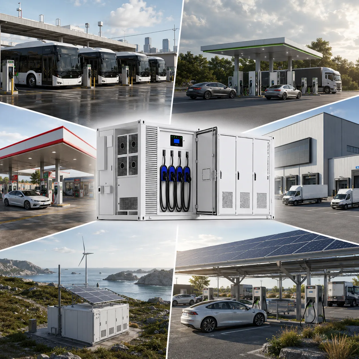
Four-Gun Charging for Operational Vehicle Fleets
Fleet and bus projects can require several vehicles to charge within the same operating period.
Four charging guns and dynamic power allocation support simultaneous charging within the 480kW total capacity.
Large Local Battery Energy Behind Fast Charging
Highway and service-area charging sites may experience changing vehicle demand across different periods.
The 1–1.5MWh battery system creates a substantial local energy buffer for the four-gun charging platform.
Add EV Charging to Existing Energy Sites
Service facilities can integrate high-power EV charging with wider local electrical loads.
The AINEGY system combines EV charging with optional PV, battery storage and additional AC output.
Coordinate Vehicle Charging and Facility Loads
Industrial sites may need to evaluate charging demand together with existing production and logistics loads.
Integrated EMS coordinates battery operation, charging sessions and compatible AC output within the configured strategy.
Hybrid Energy Inputs for Different Site Conditions
Remote charging projects may combine grid supply, optional PV input, DC recharge sources and battery storage.
The integrated ATS and EMS architecture supports coordinated hybrid operation according to project design.
480–720kW Optional Solar Input
Projects with high-capacity solar generation can configure the DC-coupled PV input around the selected model.
Four or six MPPT channels support the corresponding 480kW or 720kW optional PV architecture.
480kW Four-Gun EV Fast Charging BESS Engineering FAQ
Technical answers for fleet operators, charging-station developers, EPC teams and energy-system engineers evaluating a large battery-integrated EV charging project.
It is a hybrid-grid energy storage integrated container with built-in 480kW EV fast charging. The system combines 1MWh or 1.5MWh liquid-cooled LiFePO4 battery storage, four charging guns, dynamic charging power allocation, integrated EMS, integrated ATS, optional PV recharge, optional DC recharge and off-grid AC output.
Yes. The four charging guns support simultaneous EV charging. The system dynamically allocates the total available charging power among active charging sessions.
No. The 480kW rating is the total charging power of the EV fast charging system. Integrated control dynamically allocates that total capacity among the active charging guns according to vehicle demand, system conditions and configured limits.
Both configurations use a 480kW four-gun EV fast charging system. The 1MWh model provides 1MWh of battery energy, 500kW AC recharge, optional 480kW PV input and 500kW off-grid AC output. The 1.5MWh model provides 1.5MWh of battery energy, 750kW AC recharge, optional 720kW PV input and 750kW off-grid AC output.
The optional PV input forms a DC-coupled renewable energy path inside the integrated system. The 1MWh configuration supports up to 480kW PV input with four MPPT channels, while the 1.5MWh configuration supports up to 720kW with six MPPT channels.
It is a separate optional DC input path used to recharge the stationary battery system from a compatible external DC source. It is different from the four EV charging guns used to supply vehicles.
Yes. AINEGY EMS and ATS are integrated inside the hybrid energy storage container. They coordinate battery operation, connected energy sources, EV charging demand, grid conditions and additional AC load output according to the configured system strategy.
Yes. In addition to the primary EV fast charging function, the 1MWh configuration supports up to 500kW off-grid AC output and the 1.5MWh configuration supports up to 750kW off-grid AC output for compatible connected loads.
GBT is available, with CCS1, CCS2 and CHAdeMO offered as project options. The system supports standalone operation, with optional OCPP 1.6J for compatible charging management backend integration.
Send the expected vehicle types, daily charging sessions, simultaneous charging demand, connector standard, available grid power, optional PV data, DC recharge source information, additional AC load demand, operating strategy, communication requirements, ambient conditions and site layout.
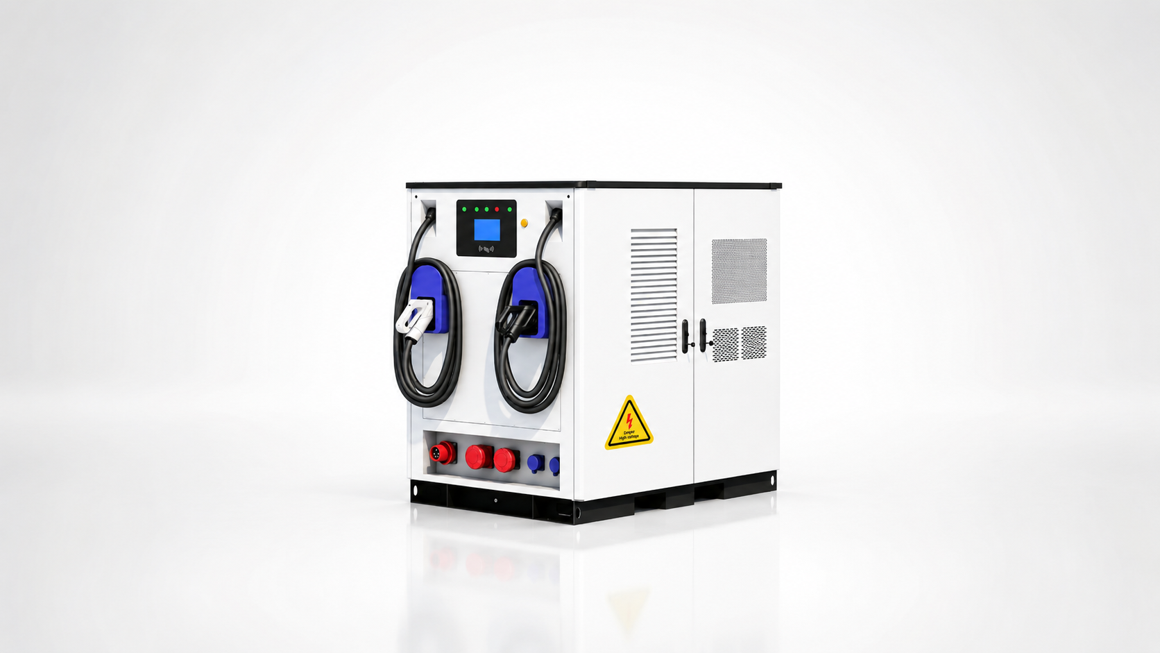
Configure Your 480kW Four-Gun EV Fast Charging BESS Container with AINEGY
Send the expected vehicle types, daily charging sessions, simultaneous charging demand, connector standard, available grid power, PV array data, optional DC recharge source, additional AC loads, communication requirements and site conditions. AINEGY will review the 1MWh or 1.5MWh battery configuration, dynamic four-gun charging strategy, integrated EMS and ATS control, recharge interfaces and project layout.