High Peak Demand
Short or recurring load peaks increase demand charges or exceed the preferred grid-import level.

Configure battery energy storage around facility loads, grid capacity, solar generation, electricity tariffs, critical loads and required operating modes.
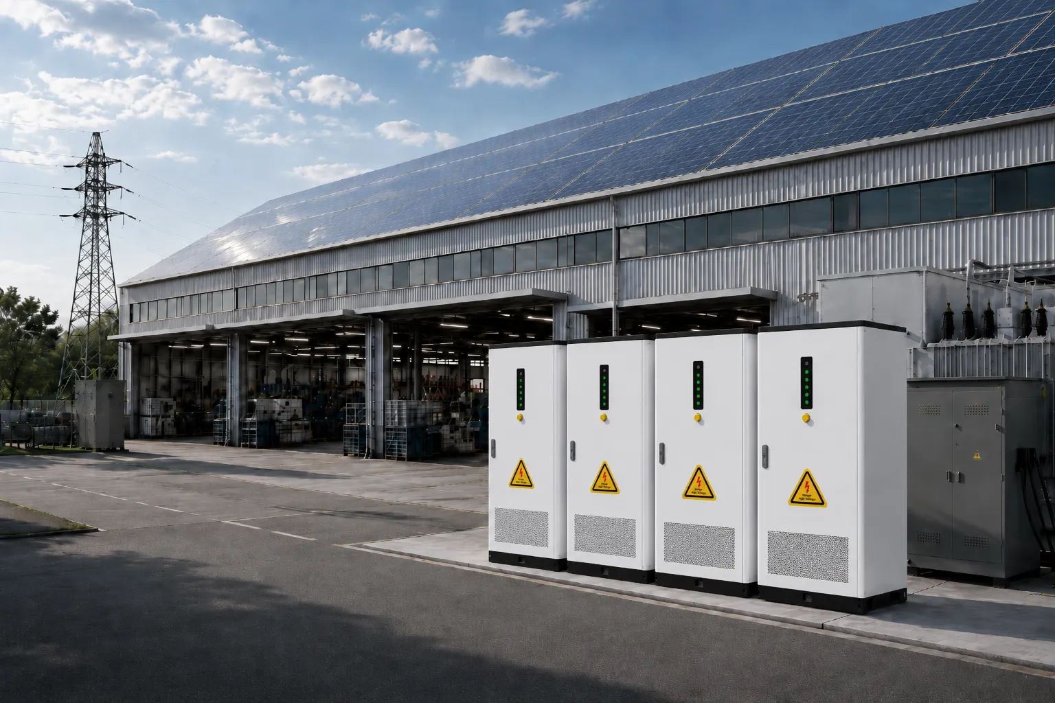 Grid + PV + BESS + Facility Loads
A commercial and industrial energy storage system stores electricity from the grid, solar PV or another configured source and supplies it to facility loads according to an EMS control strategy. A C&I BESS can support peak shaving, demand-charge management, solar self-consumption, energy time shifting, grid import limiting and configured backup power.
A suitable project normally has a measurable load, tariff, grid-capacity, solar-utilization or resilience objective. The first assessment should identify the value driver before selecting a battery cabinet or container.
Short or recurring load peaks increase demand charges or exceed the preferred grid-import level.
Electricity prices vary enough between charging and discharging periods to create an energy-shifting opportunity.
Rooftop or ground-mounted PV produces more power than the facility can use during part of the day.
New production, HVAC, refrigeration or EV charging loads cannot be added without increasing site power capacity.
Selected production, data, cooling, pumping or control loads require configured backup energy and a defined transfer strategy.
The local utility or market rewards controlled load reduction or flexible energy use and the project can satisfy participation rules.
The selected operating modes should match the facility objective, electricity tariff, connection agreement and product capability. Different AINEGY product platforms provide different functions.
The BESS discharges when site demand approaches a configured threshold, reducing the power imported from the utility during the peak interval.
EMS dispatch is coordinated with the applicable demand-charge window and billing method rather than relying on a fixed daily schedule.
Surplus PV energy can charge the battery and be used later by facility loads, subject to system limits and export rules.
The battery charges during an approved lower-cost period and discharges during a higher-cost period according to the economic strategy.
Battery power supports the facility so grid import remains near a project-defined target at the point of common coupling.
Supported hybrid configurations reserve SOC and transfer defined critical loads. Selected AINEGY systems support transfer times below 20 ms.
C&I projects should not use one universal diagram. The electrical architecture changes according to whether the site requires grid-connected energy management, solar-plus-storage or hybrid backup operation.
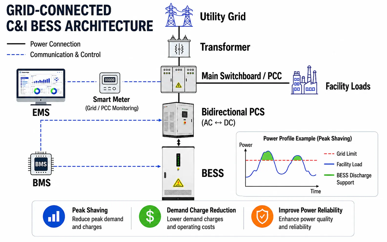
Designed for behind-the-meter energy management without relying on an off-grid operating mode.
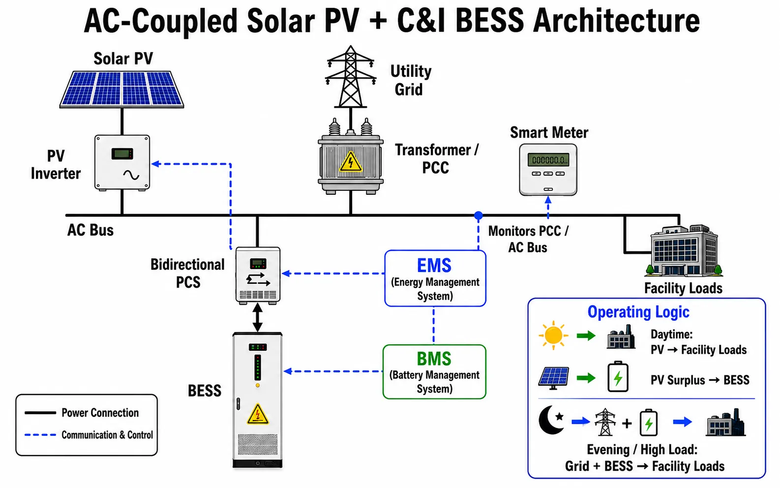
Coordinates rooftop or ground-mounted solar generation with facility consumption and battery charging.
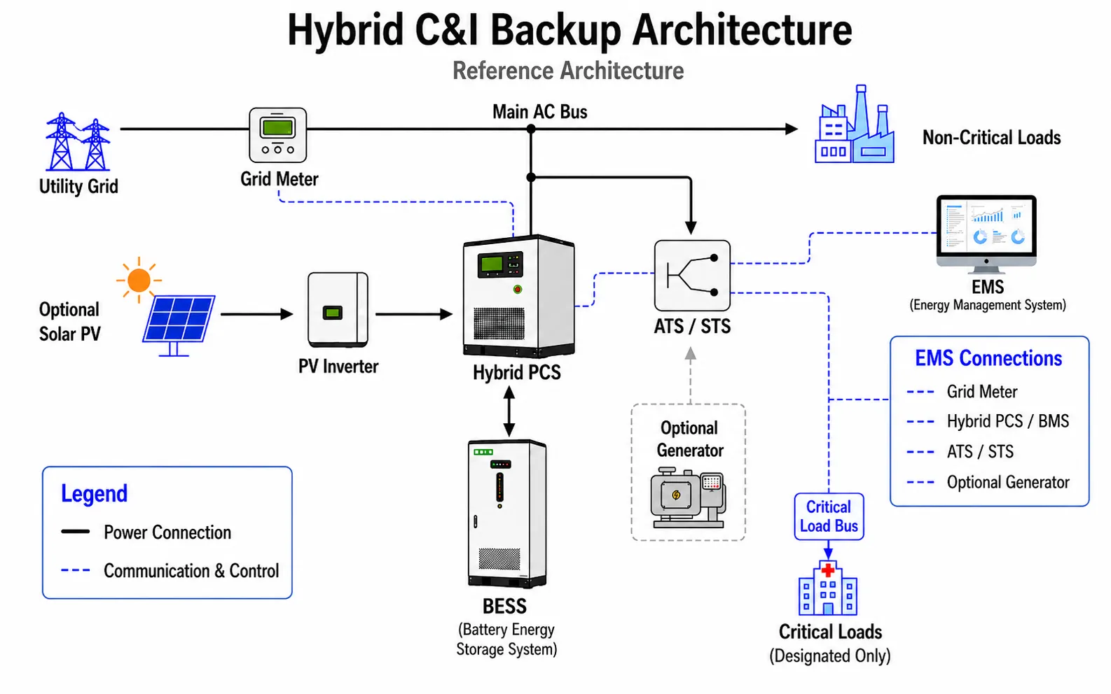
Separates critical loads and uses a compatible hybrid PCS, EMS and ATS or STS configuration for backup operation.
Detailed model selection follows the load study and architecture review. Product specifications should be taken from the corresponding model page and technical datasheet.
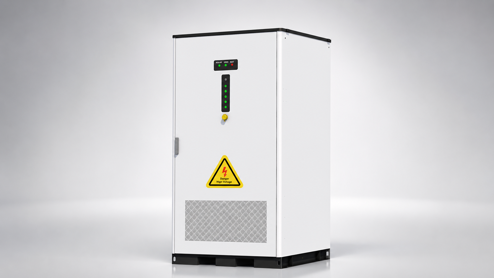
For standard behind-the-meter energy management projects where the selected power, capacity and environment match an air-cooled cabinet platform.
View Product Category →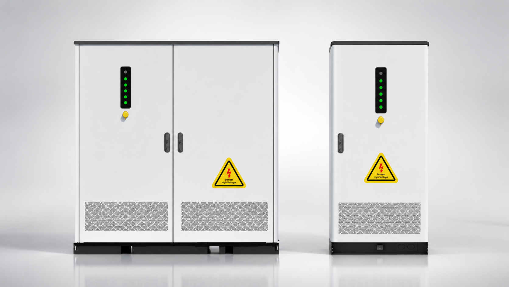
For higher-energy-density and demanding duty-cycle applications requiring a liquid-cooled thermal-management platform.
View Product Category →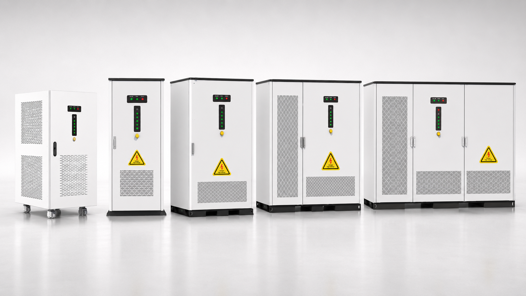
For PV integration, defined critical loads, on-grid and off-grid operation and fast transfer on supported configurations.
View Product Category →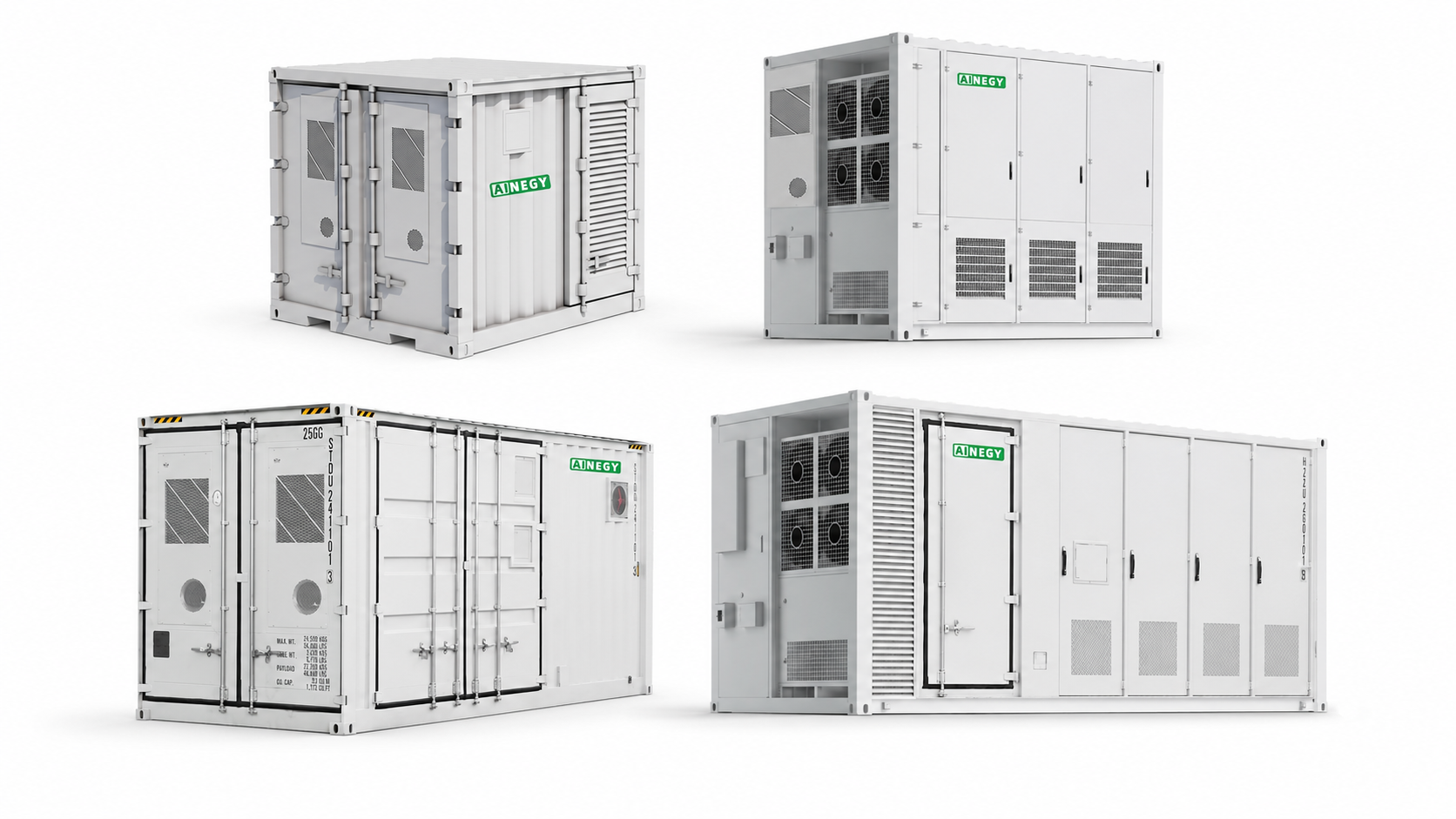
For larger facility loads, industrial parks and MWh-scale projects requiring project-specific PCS, EMS, protection and installation design.
View Product Category →AINEGY product categories are matched to the required operating modes. Grid-connected cabinets, hybrid systems, microgrid products and containerized BESS do not share identical functions.
| AINEGY Product Platform | Grid Energy Management | PV Integration | Backup | <20 ms Transfer | Off-Grid | Grid Forming / Black Start | Typical Application |
|---|---|---|---|---|---|---|---|
| Grid-Connected C&I BESS Cabinet | Yes | AC-Coupled | No | No | No | No | Peak shaving, tariff optimization, grid import limiting |
| Hybrid C&I BESS Cabinet | Yes | Yes | Yes | Supported Models | Yes | By Model | Solar-plus-storage, critical-load backup, hybrid operation |
| Solar-Diesel-BESS Integrated Cabinet / Cabin | Yes | Yes | Yes | Yes | Yes | Yes | Factory microgrids, weak-grid sites, black-start applications |
| Containerized BESS | By Configuration | By Configuration | By Configuration | By Configuration | By Configuration | By Configuration | Large C&I loads, industrial parks and MWh-scale projects |
The EMS uses site measurements and operating constraints to determine when the battery charges, discharges or preserves reserve energy.
PV supplies facility loads first. Surplus generation can charge the battery according to the EMS strategy and export restrictions.
The battery charges from the grid during an approved lower-price period when economic and operating conditions allow.
When site demand approaches the grid-import target, the BESS discharges to support the facility load.
Selected hybrid configurations reserve battery SOC and transfer the defined critical-load bus during a grid outage.
The system verifies grid voltage and frequency before returning to the configured grid-connected state.
Control decisions account for load, PV, SOC, tariffs, reserve requirements, demand limits and equipment operating constraints.
Economic value depends on the load profile, tariff, demand charges, PV generation, battery dispatch, system cost and available incentives. Research benchmarks provide context, not a project guarantee.
A practical preliminary range for suitable C&I projects before detailed simulation. Actual reduction depends on peak width, battery power, usable energy and dispatch strategy.
AINEGY planning reference; final value requires interval load data.An NREL commercial-building study reported a 23% median demand-charge reduction for storage-only systems under the study's stated sizing and tariff assumptions.
Research benchmark: NREL demand-charge study.The same research reported a 42% median demand-charge reduction for solar-plus-storage, reflecting synergy between PV generation and storage dispatch.
Research benchmark; results varied substantially across simulations.A 2025 study of 606 C&I facilities reported minimum discounted payback periods as low as 4.75 years when event-based demand response and suitable dispatch conditions were available.
Applied Energy, 2025.A published commercial project study identified a 200 kWp PV plant with 250 kWh BESS and net metering as the optimized configuration with a 6.15-year payback.
Journal of Energy Storage, 2024.For suitable C&I applications, AINEGY can evaluate configurations targeting an approximate 3–7 year payback based on site-specific tariffs, load data, cycling and incentives.
Target range, not a guaranteed result.A project-specific calculation should report estimated peak-demand reduction, annual energy shifted, PV self-consumption, annual savings, simple payback, discounted payback, NPV and IRR using clearly stated assumptions.
Power and energy capacity are separate design variables. A correct C&I BESS size must match both the maximum required load support and the duration for which that support is needed.
Power determines how much instantaneous facility load, grid-limit support, PV fluctuation or critical-load demand the BESS can serve.
Energy capacity determines how long the system can support the selected load or how much electricity can be shifted between time periods.
Interval load data is the foundation of technical and economic analysis. Missing tariff, load, grid or backup information should be identified before a final system recommendation is issued.
The EMS should make decisions from measurable site data and defined operating constraints. It is not sufficient to state that software “automatically optimizes” the system without explaining its inputs and outputs.
Data used to determine the current operating condition.
Commands issued within the authority of the selected architecture.
Strategies are selected according to project economics and resilience requirements.
System safety is established through coordinated battery, thermal, electrical, fire-protection, control and site-design measures. Certification claims must match the selected model and target market.
Monitor voltage, current and temperature across the battery hierarchy and apply model-specific protection thresholds.
Select air or liquid cooling according to product platform, duty cycle and site environment.
Coordinate switchgear, isolation, grounding and protection with the facility electrical system.
Use the fire-detection, alarm, suppression and enclosure provisions specified for the selected product.
Define communication interfaces, user permissions, remote access and alarm handling for the project.
Confirm the agreed test scope for charging, discharging, protection, communication and operating modes.
The same battery cabinet can deliver different value in different industries. The load shape, process risk and electrical infrastructure determine the correct solution.
Production peaks, motors, process loads and production-continuity requirements.
Typical focus: peak support, grid capacity and critical loads.Multiple buildings, shared transformers, distributed PV and expanding tenant loads.
Typical focus: coordinated site-level energy management.HVAC, automation, refrigeration, lighting and growing EV fleet charging demand.
Typical focus: peak control and solar-plus-storage.Continuous refrigeration loads, compressor starting and high outage sensitivity.
Typical focus: motor support and energy resilience.HVAC-dominated peaks, time-of-use tariffs and rooftop solar generation.
Typical focus: demand-charge management and PV self-use.High power density, strict continuity requirements and clearly defined critical loads.
Typical focus: resilience architecture and fast transfer.Large pumps, scheduled operation and high starting demand.
Typical focus: grid-import control and motor-load analysis.Mixed loads, extended operating hours, solar potential and critical-load groups.
Typical focus: multi-value energy management and backup.The following examples demonstrate the sizing logic. They are not final project recommendations and do not include all efficiency, reserve, degradation, short-circuit and site-design requirements.
A short recurring peak is reduced to a defined grid-import target.
Nominal battery capacity must be increased for usable SOC, efficiency, reserve and end-of-life requirements.
Midday PV surplus is stored and supplied to facility loads later in the day.
The correct capacity is limited by both available PV surplus and the load that can use the stored energy.
A defined critical-load bus is supported for a stated autonomy period.
The selected PCS, ATS or STS, motor restart requirements and transfer time must also be confirmed.
A project should progress from measurable requirements to validated equipment and operating logic.
Confirm the value driver, site conditions, interval load data, tariff, PV and backup requirements.
Model grid import, battery dispatch, energy duration and the preliminary economic case.
Define the point of connection, switchgear, PCS, EMS, ATS or STS and critical-load boundary.
Select the cabinet or container, cooling, protection, communication and applicable product options.
Complete the agreed inspections and functional tests before shipment.
Confirm transport, lifting, foundations, cable interfaces and installation responsibilities.
Verify communication, protection, charge-discharge operation and configured control modes.
Use operating data to compare actual dispatch and savings with the project assumptions.
Follow the agreed monitoring, alarm, maintenance and service responsibilities.
Review future load, PV or capacity expansion against the original electrical and control design.
A complete case study should state the country, industry, load profile, tariff, grid capacity, PV capacity, BESS power and energy, operating modes, measurement period and verified result. Reference architectures should be labelled as references rather than completed projects.
View C&I Case StudiesDirect answers to the main technical and commercial questions raised during C&I BESS project development.
A C&I energy storage system is a behind-the-meter or site-level BESS used to manage facility power and energy. It can coordinate grid power, solar PV and selected loads through PCS and EMS controls.
The system measures facility demand and discharges when grid import approaches a configured threshold. The required battery power and energy depend on the peak magnitude and duration.
Power is based on the maximum required load support, grid-import target, critical-load power, PV variation, motor demand and engineering margin.
Energy capacity is based on the required delivered energy, discharge duration, usable SOC range, system efficiency, end-of-life capacity factor and reserve requirement.
Yes. A compatible AC-coupled or hybrid architecture can coordinate existing or planned PV with facility loads and battery storage. The PV inverter, export rules and control interfaces must be reviewed.
Yes. The EMS can control battery dispatch around a grid-import target when metering, PCS power and battery energy are sufficient for the required load profile.
Hybrid AINEGY configurations can provide backup for defined loads. The critical-load boundary, required duration, reserve SOC, PCS capability and ATS or STS arrangement must be specified.
Selected AINEGY hybrid and integrated systems support transfer times below 20 ms. The applicable product model, switchgear configuration and compatible load requirements must be confirmed.
Off-grid operation requires a compatible hybrid or grid-forming system. Standard grid-connected cabinets do not automatically provide islanded operation.
A suitable project may target approximately 3–7 years, while published studies show wider results depending on tariffs, demand-response programs, system cost, incentives and operating strategy.
At least 12 months of 15-minute or hourly load data is preferred, together with electricity bills, tariff details, transformer capacity, PV data and backup requirements.
They are different thermal-management approaches. Selection depends on the product platform, energy density, duty cycle, ambient conditions, efficiency and maintenance requirements.
Applicable standards and approvals vary by product, installation and market. The selected model's certifications, local electrical rules, fire requirements and authority approvals must be confirmed.
Expansion may be possible when the original electrical capacity, communication architecture, control strategy, protection and physical layout were designed for additional units.
The EMS uses facility load, grid import, PV generation, SOC, tariffs, demand limits, reserve requirements and equipment alarms to calculate operating setpoints.
Provide the project location, application, load profile, tariff, grid voltage, transformer capacity, PV information, backup duration, installation environment and required operating modes.
Authoritative sources supporting the page's application, procurement, economics, safety and search-visibility framework.
Commercial-building study of billing-demand reduction from PV, storage and combined systems.
Open NREL Research →Analysis of demand-charge savings from commercial solar PV and energy storage.
Open NREL Research →DOE Energy Storage Handbook chapter covering applications and grid services.
Open Sandia Reference →Early-stage tasks, questions and reference points for commercial-scale BESS development.
Open DOE Checklist →2025 study of BESS dispatch, sizing, demand response and discounted payback.
Open Research Abstract →Commercial grid-connected PV and battery feasibility study with a reported 6.15-year payback case.
Open Research Abstract →Overview of UL 9540 system certification and UL 9540A thermal-runaway fire-propagation testing.
Open UL Reference →Official guidance emphasizing foundational SEO, useful expert-led content and clear technical structure.
Open Google Guidance →Send your interval load data, electricity tariff, transformer capacity, PV information, critical-load requirements and project location. AINEGY will evaluate the required power, energy capacity, system architecture and applicable product platform.