No Utility Grid
The site requires an independently controlled power system because a utility connection is unavailable or impractical.

Build a stable local power system around site loads, solar generation, diesel-generator capacity, battery SOC, grid conditions and required operating autonomy.
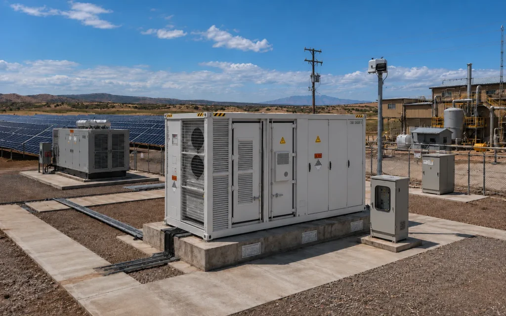 PV + Grid-Forming BESS + Diesel + Optional Grid
A hybrid microgrid is a controllable local electrical system that coordinates loads, battery storage and two or more power sources such as solar PV, diesel generators and the utility grid within a defined electrical boundary. It can operate grid-connected, separated in island mode or completely off-grid according to the designed control and protection architecture.
A hybrid microgrid is appropriate when the site must coordinate multiple power sources, maintain a local electrical system without a stable grid or reduce dependence on continuously running diesel generators.
The site requires an independently controlled power system because a utility connection is unavailable or impractical.
Voltage, frequency, outage or capacity limitations affect industrial operations even though a utility connection remains available.
Diesel generators operate for long periods and create substantial fuel, transportation and maintenance costs.
The site has useful solar resources but requires battery storage and coordinated control to manage variability and curtailment.
Pumps, compressors, production lines, communications or control systems cannot tolerate frequent uncontrolled shutdowns.
PV, diesel generators, the utility grid and BESS must operate as one coordinated system rather than as separate assets.
Microgrid design begins with the site's electrical behavior. Energy cost alone is not enough; stability, generator constraints, motor starting and load priority can determine the required system architecture.
Small or weak electrical systems can respond strongly to rapid load changes, renewable variation and generator switching.
Generators may run continuously even during low-load periods, increasing fuel use and maintenance requirements.
Remote mines, islands, oilfields and camps can face high delivered-fuel costs and supply interruptions.
Without suitable storage power, energy capacity and dispatch control, available solar generation may be limited.
Pumps, crushers, compressors and conveyors can impose short-duration power and reactive-power requirements.
Generator quantity and minimum stable loading may not match the site's changing demand and renewable output.
Weak-grid projects require controlled separation, island operation, resynchronization and restoration.
Critical production, auxiliary, residential and interruptible loads require different shedding and restoration priorities.
The correct topology depends on grid availability, renewable penetration, generator configuration, voltage level, load priority and whether the BESS must establish the local voltage and frequency reference.
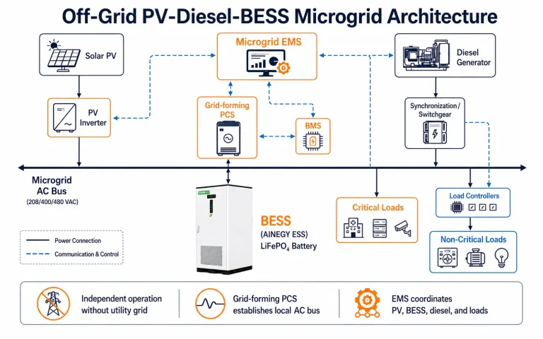
A grid-forming PCS and BESS establish the local AC bus while PV and diesel generators operate according to the microgrid EMS strategy.
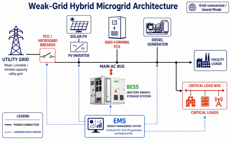
The utility remains available through a controlled point of common coupling while the local system supports grid-connected and islanded operation.
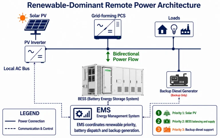
Solar PV supplies the majority of site energy while the BESS maintains the local grid and the generator provides scheduled or backup energy.
Product selection follows the electrical architecture and dynamic-load study. AINEGY's integrated cabinet and cabin platforms are intended for projects requiring confirmed grid-forming, black-start, 1C and fast-transfer functions.
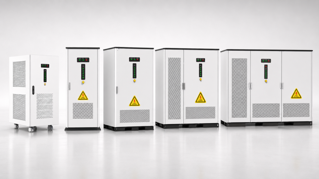
For small and medium industrial microgrids, weak-grid factories and solar-diesel retrofit projects requiring integrated control and protection.
View Product Category →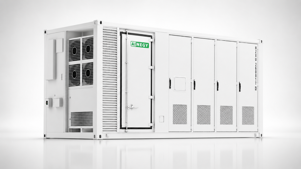
For higher-power mines, islands, oilfields and remote industrial facilities requiring grid-forming operation and multi-source coordination.
View Product Category →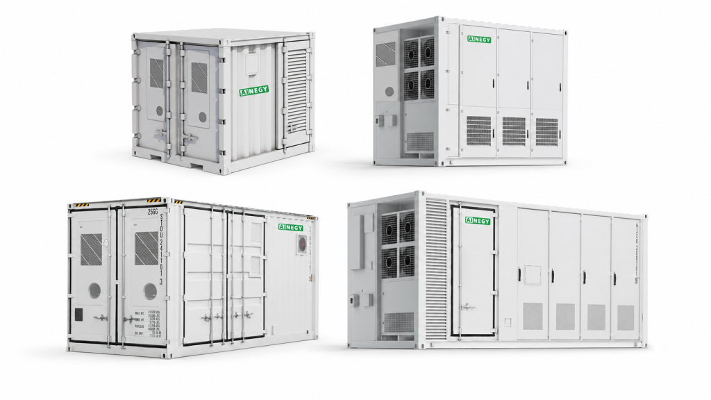
For weak-grid industrial parks, larger critical-load groups and projects requiring both grid-connected and islanded operating states.
View Product Category →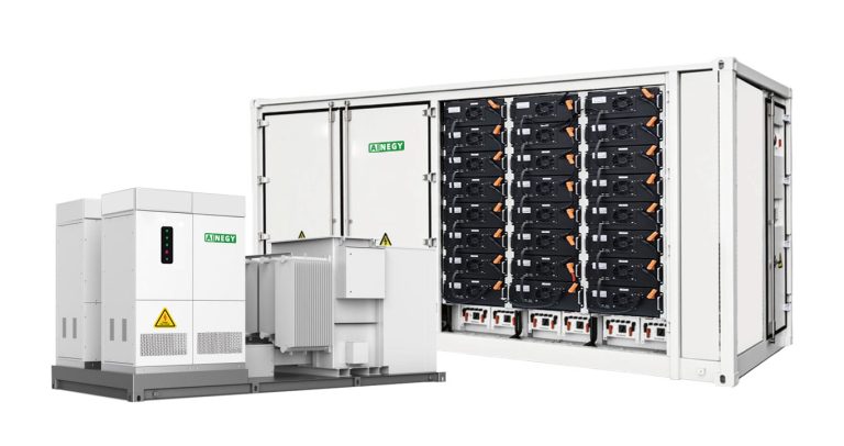
For custom MW/MWh microgrids, medium-voltage systems and multi-container projects using site-specific PCS, EMS and switchgear.
View Product Category →Confirmed functions must be mapped to the applicable product platform. Ordinary grid-connected BESS products should not be presented as grid-forming microgrid products.
| AINEGY Product Platform | Utility Grid | Solar PV | Diesel Generator | Grid Forming | Black Start | 1C Capability | <20ms Transfer | Off-Grid |
|---|---|---|---|---|---|---|---|---|
| Solar-Diesel-BESS Integrated Cabinet | Optional | Yes | Yes | Yes | Yes | Yes | Yes | Yes |
| Solar-Diesel-BESS Integrated Cabin | Optional | Yes | Yes | Yes | Yes | Yes | Yes | Yes |
| Hybrid-Grid Energy Storage Container | Yes | Optional | Optional | By Configuration | By Configuration | By Configuration | By Configuration | By Configuration |
| Configured Containerized BESS | By Configuration | By Configuration | By Configuration | By PCS Configuration | By Configuration | By Configuration | By Switchgear | By Configuration |
A grid-forming BESS establishes and regulates the local AC voltage and frequency reference when no stable utility reference is available. PV inverters, diesel generators and other resources can then synchronize to the microgrid bus according to the control strategy.
| Capability | Grid-Following Control | Grid-Forming Control | Project Significance |
|---|---|---|---|
| Existing Voltage Reference Required | Yes | No | Grid-forming control can operate without an energized utility reference. |
| Establish Local Voltage | No | Yes | Required to energize and regulate the islanded AC bus. |
| Establish Local Frequency | No | Yes | Provides the reference followed by compatible resources. |
| Independent Island Operation | Limited | Yes | Supports an electrical island when the complete system is designed accordingly. |
| Black-Start Source | Normally No | Yes | Requires auxiliary power, SOC, protection and a verified restoration sequence. |
The grid-forming PCS controls the local bus rather than waiting for another source to establish the reference.
High battery power supports rapid load changes, motor-starting contribution, renewable smoothing and staged load restoration.
1C is an important capability but does not independently guarantee black start.
The microgrid EMS coordinates energy balance and equipment constraints over time, while faster control layers maintain electrical stability and respond to sudden changes.
PV supplies active loads first and charges the BESS when battery limits and the dispatch strategy permit.
The BESS responds to short-term differences between renewable generation and demand while regulating the local bus.
When PV and battery conditions are sufficient, configured generators can stop while the grid-forming BESS maintains the microgrid.
The EMS starts a generator when SOC, forecast generation, load demand or reserve thresholds require additional energy.
A running generator may supply loads and charge the BESS within an efficient operating range when the strategy permits.
The BESS supports the local bus and manages reliance on an unstable utility connection.
After utility separation, local voltage, frequency, generation, storage and load priority are controlled within the microgrid.
Before reconnection, the controller verifies voltage, frequency, phase sequence and synchronization conditions.
Configured non-critical loads are disconnected when available generation and storage cannot support total demand.
Black start is a controlled system-restoration sequence. It requires an available battery, healthy auxiliary power, suitable switchgear, grid-forming control and a verified order for energizing transformers, auxiliaries and site loads.
The complete system must be ready before the local bus is energized.
AINEGY integrated microgrid cabinet and cabin configurations support transfer times below 20ms for compatible loads when configured with the specified PCS, switching equipment and control architecture.
Confirm the microgrid is safely separated from unavailable external sources.
Verify SOC, BMS status, auxiliaries, alarms and PCS availability.
Initiate the configured voltage and frequency control mode.
Establish the local electrical reference and energize the approved bus section.
Connect essential control, cooling, pumping and communication auxiliaries.
Restore defined loads according to their power and priority sequence.
Bring compatible PV inverters onto the established microgrid bus.
Start and synchronize diesel generation when energy balance requires it.
Reconnect lower-priority loads as available power and reserve permit.
Transfer from restoration control to the configured EMS operating strategy.
Fast electrical control, system-restoration control and long-horizon energy dispatch serve different purposes. A professional microgrid architecture defines these layers rather than assigning every function to a single EMS command.
Fast local control maintains immediate electrical behavior.
System-level control restores references and coordinates multiple sources.
Energy management schedules resources using forecasts, costs and reserve requirements.
Microgrid sizing is an iterative electrical and energy-balance process. Average load alone cannot determine BESS power, battery capacity, PV size or generator configuration.
Power must support the largest simultaneous dynamic requirement, not only the average site demand.
Energy capacity must cover the selected operating period after available PV and generator contribution are considered.
PV size must be matched to solar resource, load timing, battery charging capability and the permitted curtailment level.
Existing and new generators must be evaluated as dynamic electrical sources, not only by total nameplate power.
Fuel savings are created by changing when generators run, how heavily they are loaded and how much renewable energy the microgrid can accept without compromising reserve or stability.
Where generator limits permit, the EMS avoids unnecessary extended operation at inefficient low loading.
PV and BESS support the site while configured generators remain stopped.
A running generator can serve loads and charge the battery within a more efficient operating region.
Fast BESS response can reduce the portion of reserve that must be held by online generators.
Multi-generator plants operate only the number of units needed for load, reserve and reliability requirements.
Load forecasts, solar forecasts and SOC planning reduce unnecessary starts and improve energy scheduling.
The strongest economic drivers are often delivered fuel cost, generator efficiency, renewable resource, logistics, outage exposure and the site's ability to operate generators less frequently.
A published U.S. remote-microgrid project identified approximately 25% fuel-consumption reduction as a modeled project target.
Project target, not a universal guaranteed result.An Alaska microgrid program set a goal of at least 50% diesel reduction without increasing total lifecycle cost.
Program objective under defined project and lifecycle assumptions.AINEGY can model annual fuel, generator runtime, PV utilization, LCOE, payback, NPV and IRR using site data.
Requires hourly or sub-hourly load, solar, generator and cost inputs.The most useful initial package combines load data, resource data, generator characteristics, grid behavior, operating objectives and site constraints.
Microgrid safety depends on coordinated battery, inverter, generator, transformer, switchgear, grounding, fire-protection and control design. Protection settings must account for the fault-current behavior of inverter-based resources.
Confirm controlled separation from the utility, interconnection protection and safe reconnection.
Coordinate conventional rotating equipment with inverter-based sources and the microgrid operating states.
Monitor and protect cell, module, rack and system conditions throughout all operating modes.
Use the selected product's thermal-management, detection, alarm and suppression configuration.
Define local and remote permissions, communications, event records and fallback modes.
Verify the functions that distinguish a microgrid from a conventional BESS installation.
Each sector creates a different load, fuel, power-quality and resilience problem. Industry names alone are not sufficient for system selection.
Crushers, conveyors, pumps, ventilation and camp loads combine high motor demand with expensive delivered fuel.
Key inputs: motor starting, generator plant and fuel logistics.Limited grid capacity, seasonal demand, high fuel logistics cost and strong renewable resources require coordinated dispatch.
Key inputs: seasonal load, reserve and generator redundancy.Remote production equipment, pumps, communications and safety systems require high power availability.
Key inputs: critical loads, hazardous-area interfaces and autonomy.Production lines face weak-grid conditions, power-quality limits and restricted transformer capacity.
Key inputs: load steps, continuity and utility behavior.Large pumps and continuous treatment loads create motor-starting and scheduled-energy requirements.
Key inputs: pump curves, starting method and operating schedule.Continuous communications and computing loads require defined critical-load boundaries and reserve policies.
Key inputs: continuity level, power quality and backup duration.Temporary locations combine modular deployment, variable loads and dependence on diesel generation.
Key inputs: project duration, relocatability and load growth.Irrigation, refrigeration and processing loads can be seasonal, motor-intensive and remote from strong grid infrastructure.
Key inputs: seasonal load, pump starting and solar resource.These examples show the engineering questions that determine configuration. They are not final product selections or completed customer projects.
A high-motor-load site seeking PV priority, generator optimization and black-start capability.
Final BESS power depends on motor steps and black-start sequencing; energy depends on diesel-off target, reserve and solar profile.
A factory requiring grid support, controlled islanding and rapid transfer of defined critical loads.
The transfer architecture, reserve SOC and island duration must be confirmed using the single-line diagram and load profile.
An isolated system seeking higher renewable contribution and lower generator runtime.
Seasonal energy balance, reserve margin, generator fuel curves and reliability criteria determine the final PV and BESS configuration.
The delivery process must validate energy balance, dynamic performance, protection and operating sequences before the microgrid enters service.
Confirm objectives, electrical boundary, sources, buses and load groups.
Analyze load, grid, PV, generator, environment and operating requirements.
Model energy balance, renewable contribution, fuel and reserve.
Determine BESS power, energy, PV and generator requirements.
Develop grid-forming, dispatch, load-priority and restoration logic.
Perform load flow, protection, dynamic and black-start studies.
Select PCS, battery, EMS, switchgear, cooling and protection.
Complete agreed functional, communication and control tests.
Confirm civil, electrical, transport, installation and site interfaces.
Test grid-connected, islanded, generator and protection functions.
Test approved restoration sequences and transfer requirements.
Provide operator training, monitoring and agreed technical support.
Project pages should distinguish measured performance from commissioned operating functions and conceptual reference architectures.
Use monitored fuel consumption, generator runtime, renewable contribution, availability and the measurement period.
State the commissioned configuration, tested operating modes, supported loads and project status when complete measurement data is unavailable.
Present the design inputs, topology and intended operating strategy without describing it as a completed customer project.
Direct answers to the technical and project-selection questions commonly asked about grid-forming PV-diesel-BESS microgrids.
A hybrid microgrid is a locally controlled electrical system that coordinates loads, storage and multiple energy sources within a defined boundary and can operate connected to or separated from the utility grid.
A microgrid includes a defined electrical boundary, coordinated source and load control, protection and an independent operating capability. Solar and storage alone do not automatically provide these functions.
A grid-forming BESS establishes and regulates the local AC voltage and frequency reference when a stable external reference is unavailable.
Grid-following control normally requires an existing voltage and frequency reference. Grid-forming control can establish that reference for an islanded or off-grid bus.
Yes. AINEGY solar-diesel-BESS integrated cabinet and cabin platforms are designed for off-grid operation with confirmed grid-forming, EMS, protection and source-coordination functions.
PV supplies available renewable power, the BESS balances short-term demand and maintains the local bus, and diesel generators supply energy when SOC, load or reserve conditions require them.
The EMS increases solar utilization, creates generator-off periods, improves generator loading, reduces unnecessary starts and uses BESS response to reduce part of the spinning-reserve requirement.
Yes, when PV output, battery SOC, BESS power and reserve conditions can support the load and the configured grid-forming system maintains voltage and frequency.
The control strategy evaluates battery SOC, load demand, PV generation and forecast, reserve requirements, generator limits and the required operating autonomy.
Black start is the process of energizing the local electrical system without an existing utility voltage reference and restoring sources and loads according to a controlled sequence.
AINEGY solar-diesel-BESS integrated cabinets and cabins support black-start operation. Custom containerized systems require confirmation of the PCS, auxiliary power, switchgear and project control design.
At the battery level, 1C indicates that rated energy can correspond to rated charge or discharge power over approximately one hour under specified conditions. It supports high power response but does not alone define the complete system capability.
No. Black start also requires grid-forming PCS control, available SOC, auxiliary power, switchgear, transformer and motor-inrush assessment, protection and a verified restoration sequence.
AINEGY integrated microgrid cabinet and cabin configurations support transfer below 20ms for compatible loads with the specified PCS, switching equipment and control architecture.
Sizing uses the load profile, dynamic load steps, solar resource, generator characteristics, required autonomy, reserve policy, grid condition and operating objectives to determine power and energy capacity.
Provide site location, load profile, single-line diagram, PV resource, generator data, grid information, critical loads, autonomy, black-start and transfer requirements, and environmental conditions.
Authoritative sources supporting the microgrid definition, grid-forming control, black start, design, controller and remote-power framework used on this page.
Definition, operating states, electrical boundary and resilience role of microgrids.
Open DOE Reference →Specification of microgrid-controller functions and interaction with the electric power system.
Open IEEE Standard Page →Guidebook covering design objectives, analysis, architecture and project-development methods.
Open Sandia Guidebook →Research on inverter-based grid formation, transformer energization and staged system restoration.
Open NREL Research →Technical work on grid-forming storage for islanded systems and high renewable penetration.
Open NREL Research →Economics and deployment considerations for renewable-diesel hybrid power systems.
Open IRENA Reference →Commercial control framework for PV, BESS, generators, load sharing and load management.
Open Siemens Reference →Industry description of local generation, storage, loads and controller integration.
Open Schneider Reference →Send your load profile, solar resource, grid information, generator data, required autonomy, critical-load groups and operating objectives. AINEGY will evaluate the required BESS power, energy capacity, grid-forming architecture, generator strategy and applicable product platform.