Frequent or Extended Outages
Utility interruptions, voltage events or long restoration periods affect operations beyond the facility's acceptable risk level.

Protect defined critical loads through grid outages with project-specific battery power, backup duration, transfer time, load priority and on-grid or islanded operating strategies.
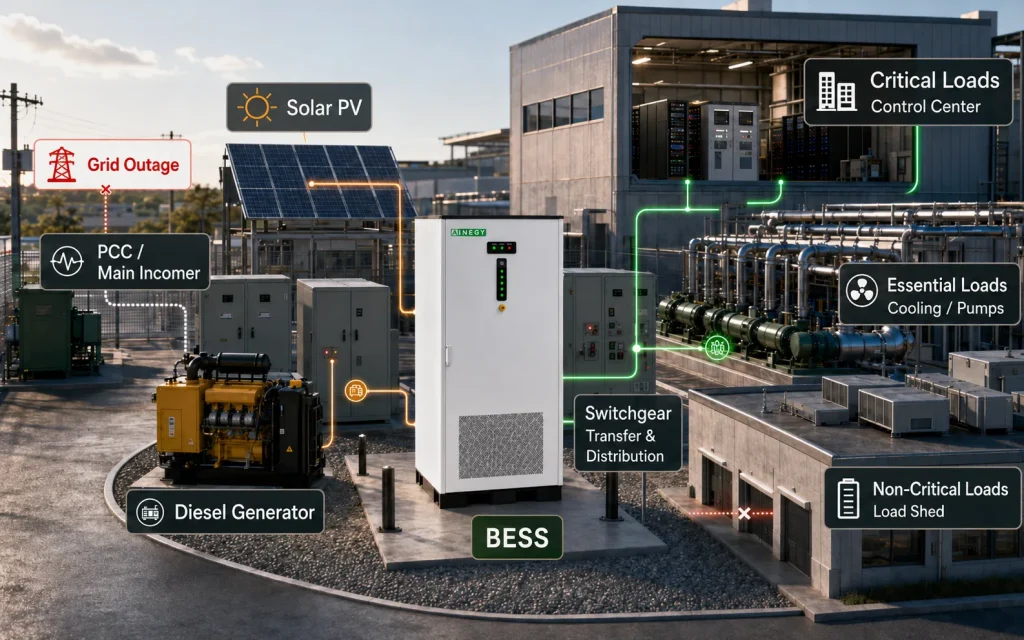 Critical Loads + BESS + PV + Generator + EMS
A critical-load backup system supplies defined electrical loads when the normal utility source is unavailable. Energy resilience extends beyond short-term backup by coordinating storage, generation, controllable loads, protection and restoration over an uncertain outage duration.
Reliability reduces the frequency or impact of everyday electrical disturbances. Backup power supplies defined loads after an interruption. Energy resilience determines how the facility isolates, continues operating, adapts to limited energy and returns to normal service.
| Requirement | Primary Objective | Typical Event | Load Boundary | Control Requirement | Useful Performance Metric |
|---|---|---|---|---|---|
| Power Reliability | Reduce interruptions and power-quality events | Voltage variation, short disturbance or equipment fault | Equipment, process or complete facility | Protection, redundancy and power-quality control | Uptime, event frequency and fault rate |
| Backup Power | Supply specified loads for a stated period | Utility outage or source failure | Defined critical-load bus | Transfer, SOC reserve and backup dispatch | Transfer time and delivered backup duration |
| Energy Resilience | Withstand, adapt and recover | Long or uncertain outage | Prioritized and controllable load groups | Islanding, energy scheduling, load shedding and restoration | Critical load served, energy not served and recovery time |
The project should start from the consequence of interruption, not from a preferred battery capacity. A suitable system has a defined load boundary, a measurable outage risk and an operating requirement that can be converted into power, energy and transfer-time criteria.
Utility interruptions, voltage events or long restoration periods affect operations beyond the facility's acceptable risk level.
Loss of power can create product scrap, cold-chain loss, data loss, equipment damage, contractual penalties or prolonged restart time.
Some loads require a UPS, others can use fast-transfer BESS, and restartable loads can be restored after a short delay.
Generator start delay, fuel logistics, maintenance, noise or inefficient low-load operation limits the existing backup strategy.
PV and generator resources can be coordinated with BESS to extend outage support and reduce unnecessary generator operation.
The facility must continue as a controlled electrical island or energize the critical bus without an available utility reference.
A critical-load register should record interruption tolerance, backup duration, power, starting behavior and restoration priority for each load. The four classes below are a practical project framework, not a universal regulatory classification.
| Project Load Class | Interruption Tolerance | Typical Protection Direction | Representative Loads | Engineering Check |
|---|---|---|---|---|
| Class A — No-Break | Near-instantaneous continuity required | Dedicated online UPS or equivalent approved system | Selected servers, controllers, safety and transaction systems | UPS topology, runtime, bypass and downstream coordination |
| Class B — Fast Transfer | Very short interruption may be tolerated | Supported hybrid PCS and compatible switching | Compatible controls, communications and electronic loads | Complete transfer event and load ride-through test |
| Class C — Restartable Critical | Short delay and controlled restart accepted | ATS, BESS or generator-backed critical bus | Pumps, cooling, selected process and production auxiliaries | Starting current, voltage dip and restart sequence |
| Class D — Deferrable | Can be shed or restored later | EMS-controlled load shedding | Nonessential HVAC, general office and deferrable production | Control interface and restoration priority |
Backup performance depends on the complete electrical system. Transfer time, battery SOC, motor starting, protection behavior and restoration logic can be more important than the battery nameplate capacity.
The complete transfer event must remain within the actual tolerance of each PLC, drive, contactor, server and process load.
A BESS used for daily energy management requires a defined resilience reserve so an outage does not begin with insufficient energy.
Pumps, compressors, chillers and transformers can require short-duration current, reactive power and voltage support above normal load.
Inverter-based fault current differs from the public grid, so protection must coordinate across both grid-connected and islanded states.
The BESS must bridge generator starting and support stable synchronization before power is shared across the critical bus.
PV can extend outage support but cannot be treated as fixed available power during nighttime or low-resource periods.
Restarting every load at once can exceed PCS, generator or transformer limits and cause a second shutdown.
PCS controls, BMS, communication, cooling, switchgear and control power are all part of the backup availability chain.
No single topology fits every load. The correct architecture depends on permitted interruption time, outage duration, available PV and generator resources, critical-load power and whether the BESS must establish the local voltage and frequency reference.
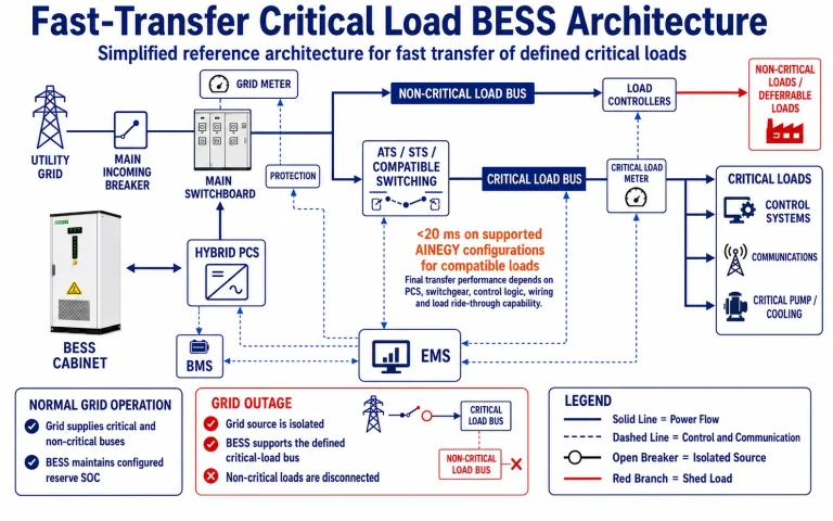
A supported hybrid BESS and compatible switching isolate the critical-load bus and continue supplying loads whose ride-through characteristics match the transfer event.
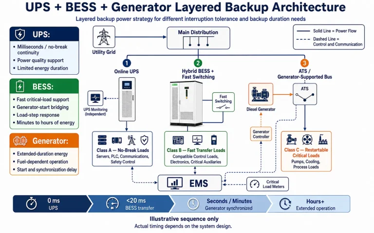
Different interruption and duration requirements are assigned to complementary resources rather than forcing one device to serve every load.
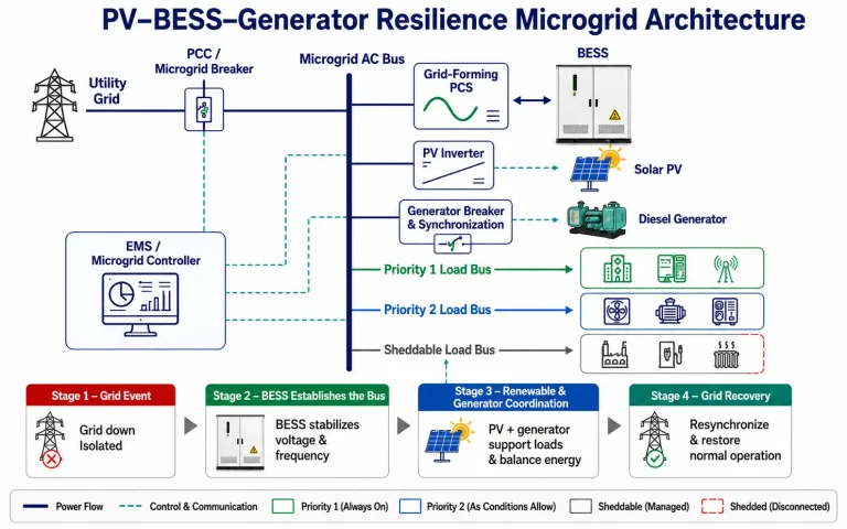
A grid-forming BESS maintains the local bus while PV, generator and prioritized loads are coordinated for longer or uncertain outages.
Product selection follows the load classification, electrical architecture and outage analysis. The product platforms below do not share identical grid-forming, black-start, transfer-time or generator-integration capabilities.
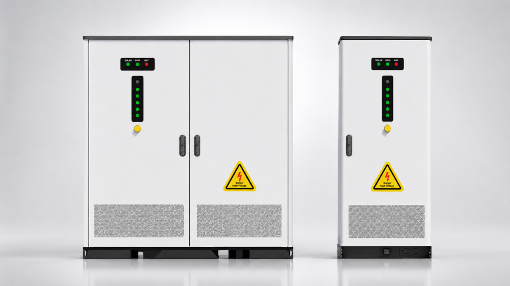
For defined commercial and industrial critical loads requiring PV integration, backup operation and supported fast transfer according to the selected model.
View Product Category →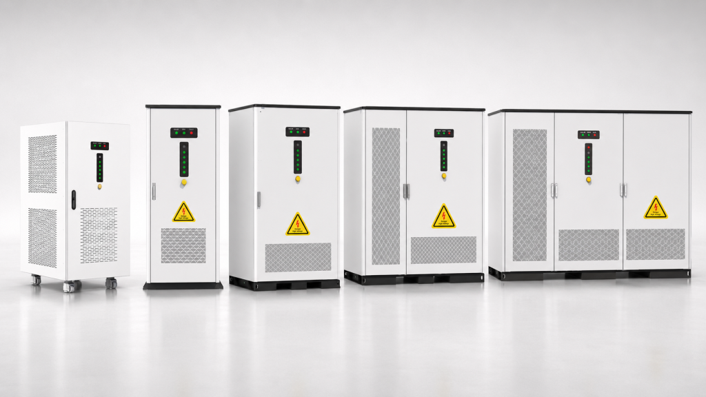
For small and medium resilience systems requiring confirmed grid forming, black start, 1C capability, PV–diesel coordination and below-20-ms transfer support.
View Product Category →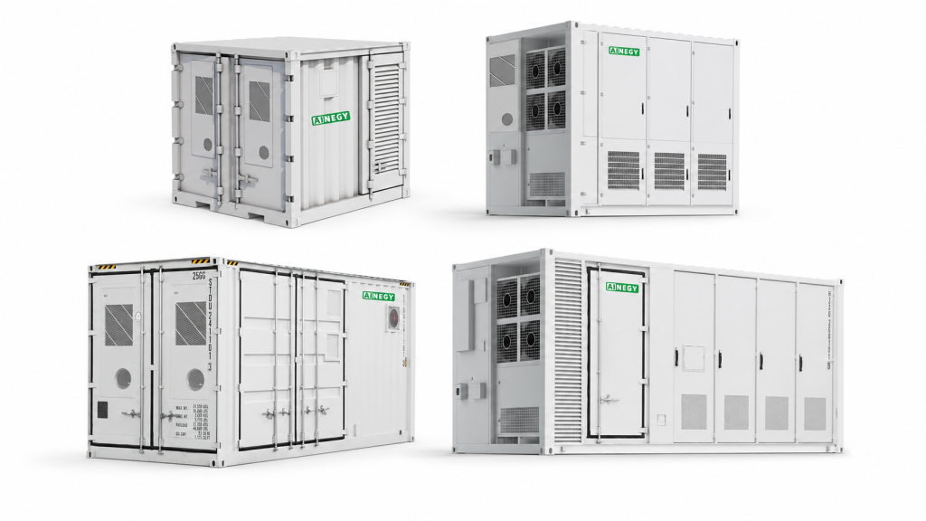
For higher-power facilities and larger critical-load groups requiring grid-forming operation, black start and coordinated PV, generator and load control.
View Product Category →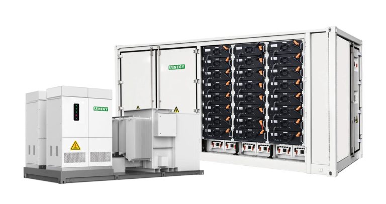
For large critical-load groups, industrial parks and medium-voltage projects using project-specific PCS, EMS, switchgear, protection and source integration.
View Product Category →Confirmed functions must be mapped to the selected platform. A standard grid-connected storage cabinet should not be presented as a grid-forming or black-start system without the required PCS, controls, switchgear and project configuration.
| AINEGY Product Platform | Backup | <20 ms Transfer | Off-Grid | Grid Forming | Black Start | Solar PV | Generator | 1C Capability |
|---|---|---|---|---|---|---|---|---|
| Hybrid C&I BESS Cabinet | Yes | Supported Models | Yes | By Model | By Model | Yes | By Configuration | By Model |
| Solar-Diesel-BESS Integrated Cabinet | Yes | Yes | Yes | Yes | Yes | Yes | Yes | Yes |
| Solar-Diesel-BESS Integrated Cabin | Yes | Yes | Yes | Yes | Yes | Yes | Yes | Yes |
| Configured Containerized BESS | By Configuration | By Switchgear | By Configuration | By PCS | By Configuration | Optional | Optional | By Configuration |
Transfer time is a complete-system characteristic. It includes grid-event detection, PCS response, switchgear operation, control logic, wiring and the load's actual ride-through capability. One millisecond value cannot prove compatibility with every load.
| Load Requirement | Typical Technical Direction | Required Confirmation | Important Boundary |
|---|---|---|---|
| No-Break or Near-Instantaneous | Online UPS or equivalent approved system | UPS topology, bypass, runtime and downstream protection | A BESS fast-transfer claim does not automatically replace a UPS. |
| Below 20 ms Compatible Load | Supported hybrid BESS and specified switching | Product model, complete transfer waveform and load test | Applies only to compatible loads and supported configurations. |
| Seconds-Level Interruption Accepted | ATS with BESS or generator-backed bus | Restart behavior, process sequence and transfer settings | Contactors, drives and controls may require separate analysis. |
| Deferrable Load | EMS load shedding and delayed restoration | Control interface, authority and restoration priority | Restoration must remain within available power and reserve. |
The operating sequence should be defined before equipment selection. Normal energy management, grid-event transfer, generator coordination and grid restoration use different control states and different acceptance criteria.
The EMS preserves the configured minimum SOC while coordinating approved daily energy-management functions.
Protection and control identify unacceptable voltage, frequency or source conditions and initiate the approved isolation sequence.
The BESS enters the configured backup or grid-forming state and supplies the defined critical-load boundary.
Dedicated UPS equipment continues to support loads whose interruption tolerance is shorter than the BESS transfer event.
The BESS bridges the start delay and supports the local bus until the generator is ready to share power.
Compatible PV reconnects to the energized local bus and supports loads or battery charging within operating limits.
The EMS removes deferrable groups when available power, energy or reserve cannot support the complete load.
Loads are reconnected according to priority, inrush and available source capacity rather than all at once.
The controller verifies utility conditions and returns sources, loads and battery SOC to the normal strategy.
A resilience system must define which loads remain energized, which loads can be removed and how each group is restored. Priority names should be tied to actual breakers, contactors, PLC points or building-control interfaces.
Safety, control, communications and essential auxiliaries.
Core process, refrigeration, pumping and production continuity.
Supporting production and selected HVAC or facility services.
Nonessential and deferrable loads.
Black start is a controlled system-restoration capability, not a battery discharge-rate claim. It requires the complete electrical and control system to energize the critical bus safely without an existing utility reference.
The system must confirm source, control, protection and load readiness before energizing the local bus.
Reconnection is permitted only after the utility source and microgrid satisfy the configured synchronization conditions.
Verify safe separation from the unavailable utility source.
Check SOC, BMS, alarms, auxiliaries and PCS status.
Establish the configured local voltage and frequency reference.
Apply power to the approved bus section and essential control auxiliaries.
Connect the highest-priority loads within the available power limit.
Reconnect compatible PV after a stable local reference is established.
Start and synchronize generation when energy balance requires it.
Reconnect lower-priority loads according to power and reserve.
Transfer from restoration logic to the approved outage strategy.
Resynchronize and recover the battery reserve after grid restoration.
PCS power must support both steady-state load and the most demanding dynamic event. Adding the nameplate ratings of the critical loads is not sufficient when motors, transformers, load steps or reactive-power requirements are present.
Use the greatest simultaneous requirement rather than an average load value.
The selected PCS and switchgear must satisfy active, apparent and reactive-power requirements under the actual site conditions.
Battery energy is based on the cumulative energy deficit during the outage, not only the instantaneous load. The calculation must include auxiliaries, reserve, credible PV and generator contribution, efficiency and end-of-life capacity.
Calculate the time-series energy that must be supplied by the battery after other credible sources are considered.
Convert the required delivered energy into a nameplate capacity using the approved operating assumptions.
BESS provides fast power and energy management, PV can replenish energy during available solar periods, and generators provide extended energy. A resilient design coordinates these resources instead of treating them as independent backup devices.
Supports immediate electrical continuity and local-system stability.
Extends available energy when the resource and system architecture permit.
Provides energy for long outages and low-solar periods.
A fixed backup-hour claim describes only one operating point. Professional resilience analysis tests outage duration, outage start time, load variation, resource availability and component status, then reports how much critical service is maintained and how the system recovers.
Percentage of required critical power and energy delivered during the modeled or measured outage.
The energy demand that remains unserved after storage, PV, generator and load-priority actions.
Maximum supported duration under a defined load, resource, reserve and equipment-availability scenario.
Probability of supporting a defined outage when it begins at different times of day and different battery SOC states.
Measured time from the grid event to the approved islanded operating state for the applicable load group.
Elapsed time required to energize and stabilize the required priority groups after isolation or black start.
Lowest SOC reached while respecting the configured control reserve and restoration requirement.
Generator operating hours, starts, loading and fuel consumption during the resilience event.
A resilience project should compare lifecycle cost with the financial and operational consequences of an outage. Electricity-bill savings may contribute value, but they should not be used as the only justification for protecting critical operations.
Estimate lost production, product scrap, inventory loss, data and transaction loss, restart labor, equipment damage and contractual penalties for each outage scenario.
Use facility records and process-owner estimates.Compare UPS-only, generator-only, BESS-only, PV-plus-BESS, layered backup and full resilience-microgrid alternatives using consistent assumptions.
Include replacement, fuel, maintenance, testing and degradation.Evaluate demand management, PV self-consumption and operating savings without compromising the minimum SOC and availability required for resilience.
Daily cycling must remain consistent with the outage reserve policy.A quotation based only on total facility load and required hours is not an engineered backup design. The initial package should define the electrical boundary, interruption tolerance, dynamic loads and existing backup resources.
Applicable standards and certifications depend on the selected product, UPS, transfer equipment, generator, installation country and local authority. The project must verify model-specific approvals rather than presenting one standards list as universal compliance.
Confirm the UPS product and installation requirements for the applicable market.
Confirm product, installation and fire-safety requirements for the selected BESS.
Transfer devices must be selected and coordinated for the actual source and load arrangement.
Define controller functions, test methods, planning and protection for grid-connected and islanded states.
Confirm generator performance, protection, synchronization and standby-power requirements.
Resilience also depends on secure and available local control.
The industry identifies the operating context, but the actual backup architecture is determined by the loads, interruption tolerance, restart sequence and available energy resources.
Control systems, process cooling, production auxiliaries, motors and controlled shutdown requirements.
Primary studies: load steps, motor starting and restart cost.UPS-backed computing and communications combined with BESS and generator support for longer-duration energy.
Primary studies: no-break boundary, runtime and redundancy.Compressors, refrigeration controls, circulation equipment and inventory-temperature protection.
Primary studies: thermal hold time and compressor restart.Critical equipment, laboratories, controls and facility services subject to local regulatory and emergency-power requirements.
Primary studies: code requirements and load classification.Pumps, treatment processes, disinfection, instrumentation and communications.
Primary studies: motor load, operating sequence and minimum service.Control, safety, communications, pumping and remote production equipment.
Primary studies: hazardous interfaces, autonomy and black start.Security, communications, lighting, cold chain, operating control and selected vehicle infrastructure.
Primary studies: multiple load groups and restoration sequence.Emergency coordination, communications, critical buildings and community support services.
Primary studies: resilience target and multi-building boundary.These examples demonstrate the engineering questions that must be resolved. They are not final product recommendations and do not include all SOC, efficiency, degradation, protection, inrush and site-design requirements.
A defined production and control bus requires rapid transfer and two hours of battery support.
Final nominal capacity requires usable SOC, efficiency, reserve, end-of-life capacity and actual load variation.
BESS supports refrigeration and controls while a generator provides extended energy.
The energy model must include thermal hold time, PV availability, fuel, generator loading and staged compressor restoration.
Different load classes are assigned to UPS, BESS and generator layers.
Final design requires the UPS boundary, generator start sequence, BESS reserve and downstream protection review.
The project should progress from measurable interruption requirements to verified transfer, islanding, load control and duration performance.
Define the safety, production, data and service consequences of power loss.
Record power, duration, interruption tolerance, starting behavior and priority.
Collect interval data and event information at the proposed electrical boundary.
Confirm UPS, generator, switchgear, PV and control-system capability.
Calculate steady load, dynamic events, outage energy and required reserve.
Establish the critical bus, PCC, transfer devices and source interfaces.
Perform load flow, short circuit, protection, motor and transient reviews.
Define reserve, shedding, restoration, generator and PV control states.
Verify communication, modes, alarms, interlocks and agreed control sequences.
Complete foundations, switchgear, cabling, controls and source interfaces.
Test supported transfer, load boundaries and islanded operation.
Test the approved restoration sequence where black start is required.
Verify synchronization, dispatch, load sharing and fallback modes.
Confirm the agreed critical-load and energy-performance acceptance criteria.
Provide procedures, alarms, manual controls and emergency responsibilities.
A complete case study should state the normal site load, defined critical load, required transfer time, required duration, BESS power and energy, UPS and generator configuration, PV capacity, load priorities, commissioning tests, measurement period and verified results. Reference configurations should not be presented as completed projects.
View Critical Load Case StudiesEngineering answers to the main load-classification, transfer, sizing, islanding and operating questions raised during resilience-system development.
A critical load is an electrical load whose loss creates an unacceptable safety, operational, financial or compliance consequence. It should be identified by load power, interruption tolerance, required duration, starting behavior, restart method and restoration priority rather than by industry name alone.
Backup power supplies defined loads for a specified period after the normal source is lost. Energy resilience also includes fault detection, islanding, load prioritization, energy management, extended outage operation, black start where required and controlled restoration to normal service.
Create a critical-load register and classify each load by maximum permitted interruption, required operating duration, safety impact, production impact, starting current, restart sequence and whether the load can be shed or delayed. The backup boundary should include only loads justified by those requirements.
No. Some control, computing or safety loads may require a dedicated online UPS, while other critical loads can tolerate a transfer below 20 ms, a short ATS delay or staged restart. The protection method should match the actual ride-through capability of each load.
No. A UPS is designed primarily for near-instantaneous continuity and power conditioning for compatible loads. A BESS can provide longer-duration energy, economic dispatch, PV coordination and island operation, but its transfer time, waveform, overload and protection characteristics must be matched to the load.
Only after a load-specific engineering review. No-break loads may still require a UPS even when a BESS is installed. A layered design often uses the UPS for instantaneous continuity, the BESS for immediate and medium-duration support, and a generator for extended energy.
Selected AINEGY hybrid C&I systems and the solar-diesel-BESS integrated cabinet and cabin support transfer times below 20 ms when configured with the specified PCS, switching equipment and control architecture. The applicable model and load compatibility must be confirmed.
A compatible load can tolerate the complete transfer event, including voltage deviation, frequency deviation, phase behavior and the actual interruption produced by detection, control and switching. Motor drives, contactors, PLCs, servers and process equipment may have different ride-through limits and must be reviewed separately.
BESS power is based on the highest requirement among continuous critical load, the largest simultaneous load step, motor-starting contribution, transformer energization, islanding support and required battery charging power, with allowance for power factor, short-term overload and site derating.
Calculate the energy required by the critical loads and auxiliaries over the outage period, subtract credible PV and generator contribution, add the required reserve, and then correct for usable SOC, conversion efficiency and end-of-life capacity. A simple kWh divided by kW calculation is only a preliminary estimate.
Actual duration changes with the battery SOC when the outage begins, load variation, auxiliary consumption, ambient temperature, battery aging, converter efficiency, solar availability, generator status and the load-shedding strategy. Final duration should be simulated against time-series data.
The EMS follows the configured resilience policy. It may immediately shed lower-priority loads, reduce the supported load boundary, start a generator, preserve a minimum control reserve or prevent restoration of nonessential loads until sufficient energy is available.
Only when the PV inverter, protection and control architecture are compatible with island operation and a local voltage and frequency reference is available. Ordinary grid-following PV normally disconnects during an outage and cannot independently energize the critical-load bus.
The BESS supports loads during generator starting, responds to rapid load changes, maintains the local bus and can reduce inefficient low-load generator operation. After synchronization, the EMS allocates load and battery charging according to SOC, generator limits, fuel strategy and reserve requirements.
Yes, but only a black-start-capable configuration can energize the local system without an external voltage reference. This requires a grid-forming PCS, available battery SOC, auxiliary power, isolation, suitable switchgear, protection and a verified restoration sequence.
Loads are assigned priorities and controlled through breakers, contactors, PLCs or building and process control interfaces. When available power or energy falls below the reserve requirement, the EMS sheds the lowest-priority groups first and records the event for controlled restoration.
They may be able to, but motor starting must be studied. The design must consider starting current, power factor, voltage dip, PCS overload capability, generator contribution, transformer impedance and the sequence in which motors and other loads are restored.
The controller verifies utility voltage, frequency, phase sequence and synchronization conditions before closing the point-of-common-coupling device. Loads and sources are then returned to the normal operating strategy in a controlled sequence.
Yes, when the system is sized and controlled appropriately. The BESS can create generator-off periods, absorb PV variation, serve low-load intervals and operate the generator closer to an efficient loading range, but the result depends on load, fuel, PV, reserve and generator constraints.
Provide the critical-load register, interval load profile, single-line diagram, transformer and switchboard data, interruption and duration requirements, motor information, existing UPS and generator details, PV data, outage history, site conditions and the required operating modes.
Authoritative sources supporting the page's critical-load, resilience, microgrid, transfer, protection and safety framework.
Electrical boundaries, island operation, resilience and controllable distributed-energy resources.
Open DOE Reference →Critical-load identification, design objectives, architecture and project-development methods.
Open Sandia Guidebook →Time-series assessment of outage survivability, load, solar generation and battery state of charge.
Open NREL Research →Lifecycle optimization and critical-load survival using PV, storage and generators.
Open NREL Reference →Specification of microgrid-controller functions and system interaction.
Open IEEE Standard Page →Microgrid protection design for grid-connected and islanded operating modes.
Open IEEE Standard Page →UPS safety, continuity and compliance considerations for protected loads.
Open UL Reference →Installation risk-mitigation framework for stationary energy storage systems.
Open NFPA Reference →Send your critical-load list, interval load profile, single-line diagram, transfer-time requirement, required backup duration, existing UPS, generator and solar information. AINEGY will evaluate the required BESS power, battery capacity, operating architecture, load priorities and applicable product platform.